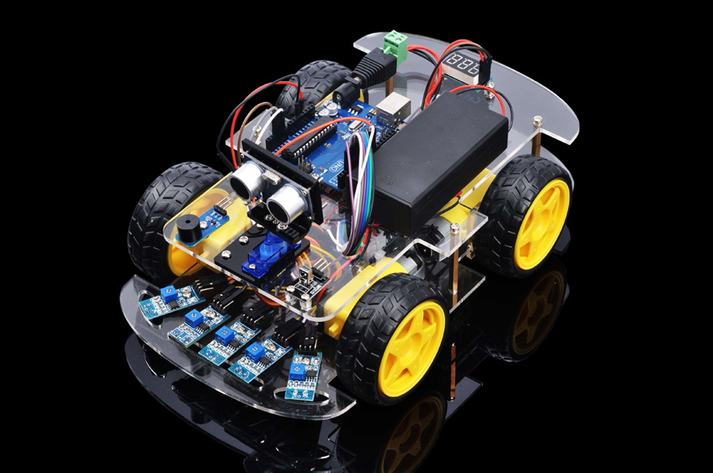
In this lesson, we will add 5 black/white tracking sensors to the framework built in Lesson 1. If you have not completed installation in Lesson 1, please review Lesson 1
The software in this lesson will read data from these 5 black/white tracking sensors and automatically guide the smart car to move along the black track line in the white ground.
Parts and Devices:
Device Name
picture
qty
Screw Number
Tracking sensor module
5
M3*10 screw x5
M3 nuts x5
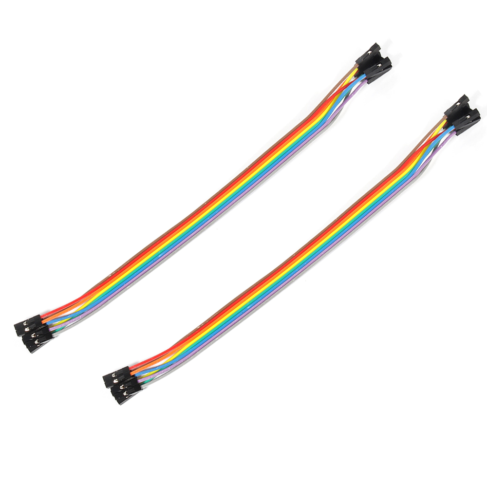
1pin male to 5 pins female jumper wires
2
Lower chassis
1
M3*5 screw x5
Copper pillar x5
Upper chassis
1
M3*5 screw x5
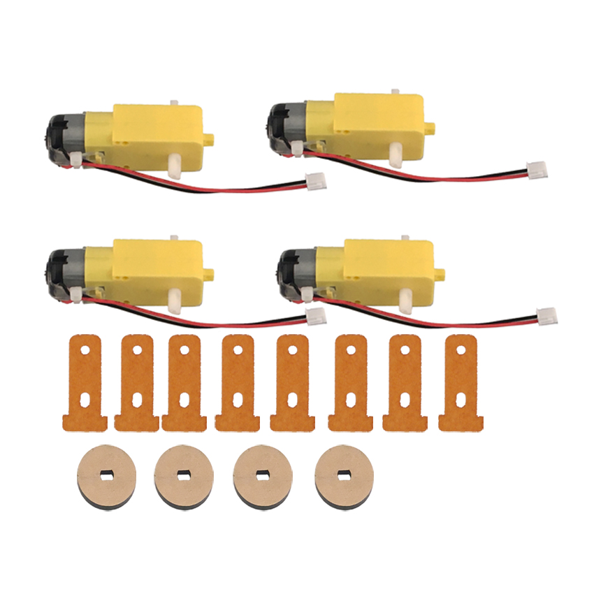
Gear Motor with wires
(Acrylic fastener for Gear Motor x8
Velocity encoder x4)
4
M3*30 screw x8
M3 nuts x8
Wheel
4
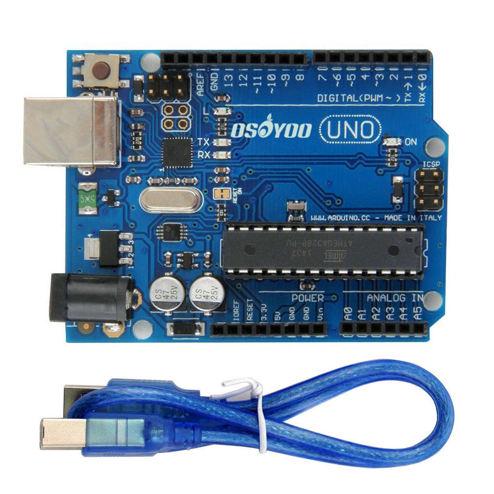
UNO R3 board for Arduino with USB cable
1
M3*10 screw x4
M3 nuts x4
Transparent Washer x4
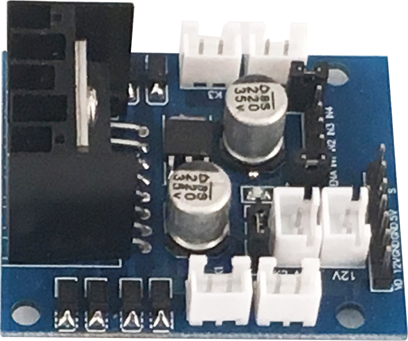
OSOYOO MODEL X motor driver module
1
M3*10 screw x4
M3 nuts x4
Transparent Washer x4
Box for 18650 3.7V battery
1
M3*10 screw x4
M3 nuts x4
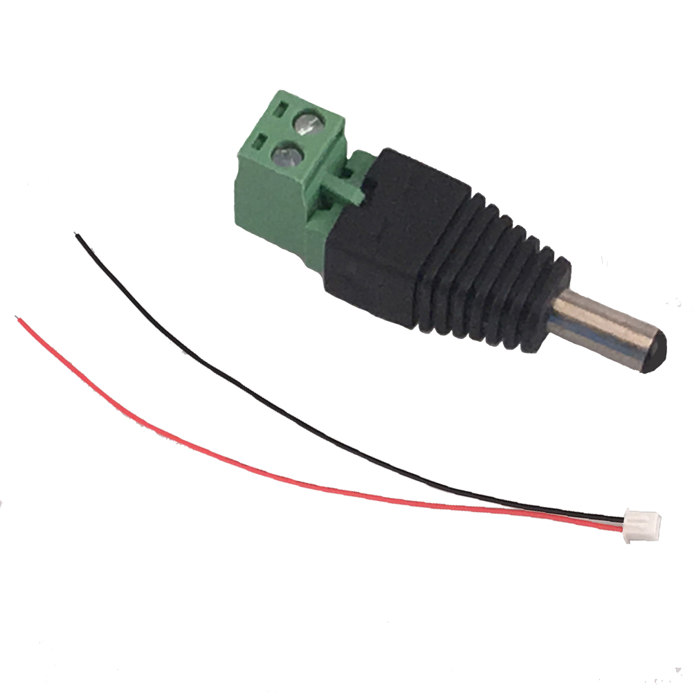
DC power connector with wires
1
Voltage meter
1
M3*10 screw x2
M3 nuts x2
Transparent Washer x2
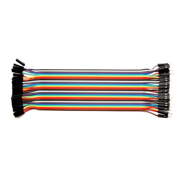
Jumper wires(female to female)
some
Jumper wires(male to female)
some
Cross screwdriver
1
Hardware Installation:
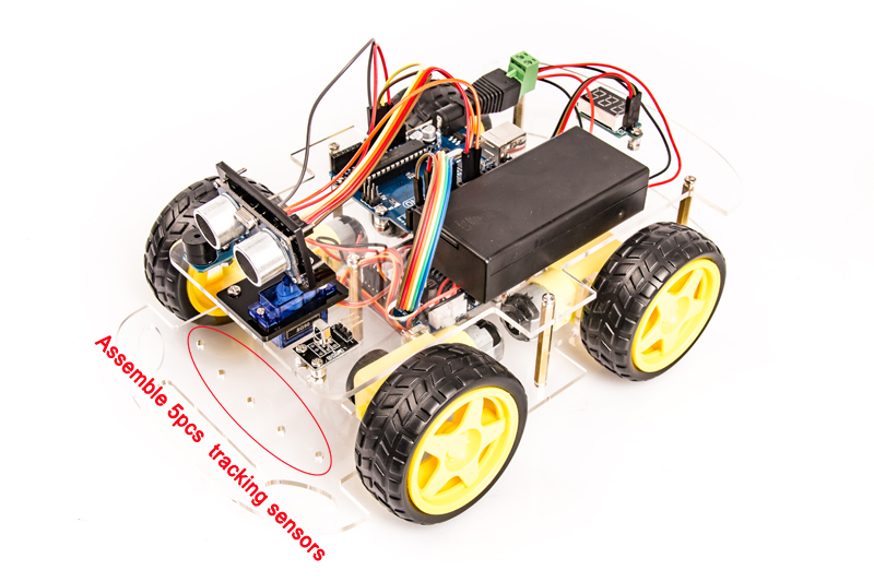
1) Install the smart car basic framework as per Smart Car Lesson 1. If you have already completed installation in Lesson 1, Lesson 2 and Lesson 3, just keep it as is. No need to remove any module installed in Lesson 2 and Lesson 3 . You can assemble tracking sensor modules into empty holes at the front of lower chassis .
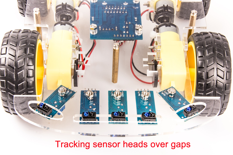
2) Fix tracking sensor module on lower chassis with 5pcs M3*10 screw and M3 nuts. Make sure that every sensor head is over the gaps at the front side of lower chassis so that the sensor can detect black lines in white ground.
3) From left to right, connect the D0(D zero) pin in tracking sensor module to D3, A1, A2, A3, D10 pin in UNO board. Remember: DO NOT remove any existing wires installed in Smart Car Lesson 1 . Use 1pin male to 5 pins female jumper wires to connect VCC and GND of 5pcs tracking sensor modules. Connect VCC of tracking sensor module to 5V in UNO board, GND to GND. As the following photo shows:
Software Installation: Step 1: Install latest Arduino IDE (If you have Arduino IDE version after 1.1.16, please skip this step). Download Arduino IDE from https://www.arduino.cc/en/Main/Software?setlang=en , then install the software.
Step 2: Download Lesson 4 tracking smart car sample code from https://osoyoo.com/driver/smartcar-lesson4.zip , unzip the download zip file smartcar-lesson4.zip, you will see a folder called smartcar-lesson4 .
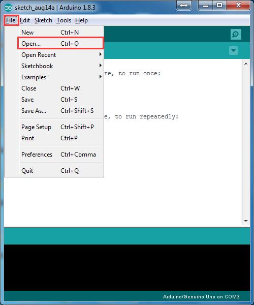
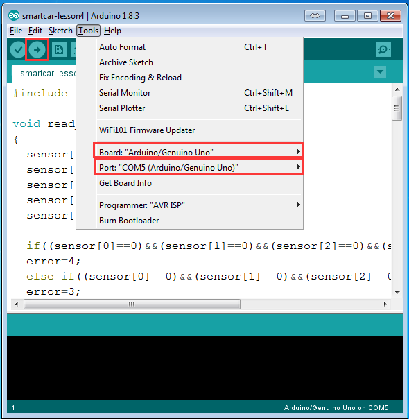
Step 3: Connect UNO R3 board to PC with USB cable, Open Arduino IDE -> click file -> click Open -> choose code “smartcar-lesson4.ino” in smartcar-lesson4 folder, load the code into arduino.
Step 4: Choose corresponding board/port for your project,upload the sketch to the board.
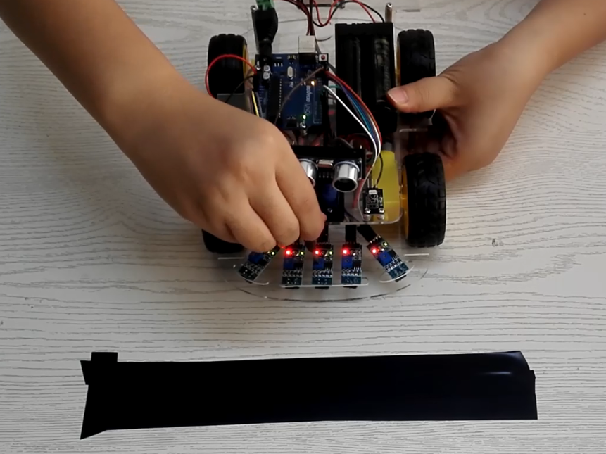
Step 5: Adjust the sensitivity of tracking sensor modules. Turn on and hold the car and adjust the potentiometer on the tracking sensor with cross screwdriver until you get the best sensitivity status: the signal indicate LED light will turn on when sensor is above white ground, and the signal LED will turn off when the sensor is above black track
Testing:
Prepare a black track (the width of the black track is more than 20mm and less than 30mm) in white ground. Please note, the bend angle of track can’t be larger than 90 degree. If the angle is too large, the car will move out of the track.
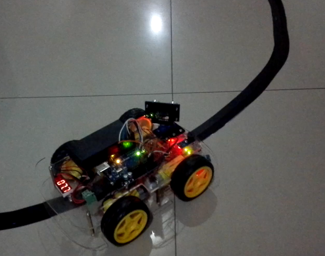
Turn on the car and put the middle of tracking sensor module facing over black track, and then the car will move along the black track.
Trouble Shooting:
If your car can move but does not follow the black track line, normally it means
your tracking sensors connection to Uno board has some problem. To help use to
find out which sensor connection is wrong, we developped following diagnosis
code to test the sensors.
After load above code to Arduino, open the serial monitor window in upper right corner of your Arduino IDE. Now put a white paper and use a black mark pen to
draw a one cm wide black line. We need use this black line to test each sensor signal received by Arduino board.
When you put black line under Left5 sensor (1st sensor frome right), and other 4 sensors all above white paper, Now Left 5 Sensor Green LED should be off. the Serial monitor will show ‘0 0 0 0 1’
as per following picture.
If Serial monitor does not show 0 0 0 0 1(i.e it shows 0 0 0 0 0 instead), it means Left5 sensor connection to UNO board is wrong. Read Hardware Installaing Step 3,
we found that Left5 should connect to D10. So we need check Left 5 sensor connection jumper wire to UNO board D10, and see if the wire is loose or not connected properly.
Repeat above procedure, put black line paper under Left 4, Left 3, Left2 and Left 1 sensor. you will find which sensor connection is wrong. Afte all sensor connection is connected
properly, your tracking program will work properly.
The steps from the previous lesson have wires the get connected into UNO board GND and other slots and now it says to connect wires to the same place again… What should I do? Please reply Asap i need to finish it by thursday
One of my sensors has a bad LED. I can run test and view serial monitor to see when sensor is seeing black or white, and adjust for proper sensitivity, but the LED never lights up. Is it possible to get a replacement sensor? [email protected]


The steps from the previous lesson have wires the get connected into UNO board GND and other slots and now it says to connect wires to the same place again… What should I do? Please reply Asap i need to finish it by thursday
Also, can we not use the Line tracking and obstacle avoidance at the same time?!!!
You can follow our lesson 5 to change the working mode between Line tracking and obstacle avoidance:
https://osoyoo.com/2017/05/14/wifi-control-smart-car/
One of my sensors has a bad LED. I can run test and view serial monitor to see when sensor is seeing black or white, and adjust for proper sensitivity, but the LED never lights up. Is it possible to get a replacement sensor? [email protected]