In previous lesson, we’ve learned how to output Raspberry Pi data through IIC (sometimes call I2C) and display characters in 1602 LCD . This lesson, we’ll combine our knowledge learnt from Lesson 11 and Lesson 13. We will use a potentionmeter to change voltage, convert the voltage analog signal to digit signal through MCP3008 and send it to Pi via SPI. Then Pi will send voltage data via I2C and display data on 1602 LCD screen.
Hardware Preparation:
1 * Raspberry Pi
1 * Breadboard
1 * Potentiometer(10kΩ)
1 * IIC 1602 LCD
Several jumper wires
Software Preparation Note: In this lesson, we remotely control raspberry pi via PuTTy on PC. To learn how to config raspberry pi, please visit lesson 1: getting started with raspberry pi.
Potentiometer Work Principle
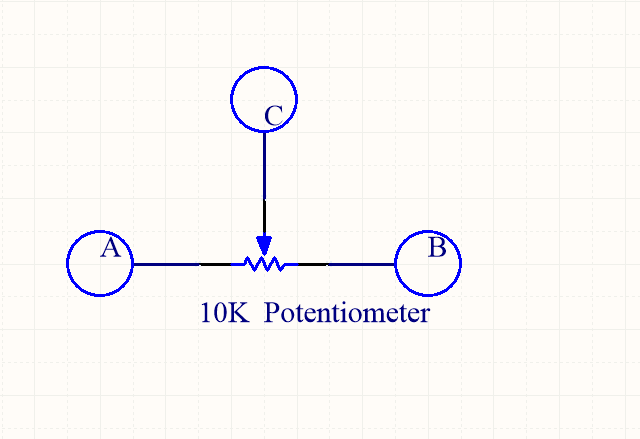
A Potentiometer is an adjustable resistor with three-terminal: two end terminals and a wiper. it could create a variable resistor using one of the end terminals and the wipers by sliding wiper to adjust the resistor value. for more information ,please click here.
The construction and working of a Potentiometer can be understood from the below diagram, A and B are end terminals, C is wiper.
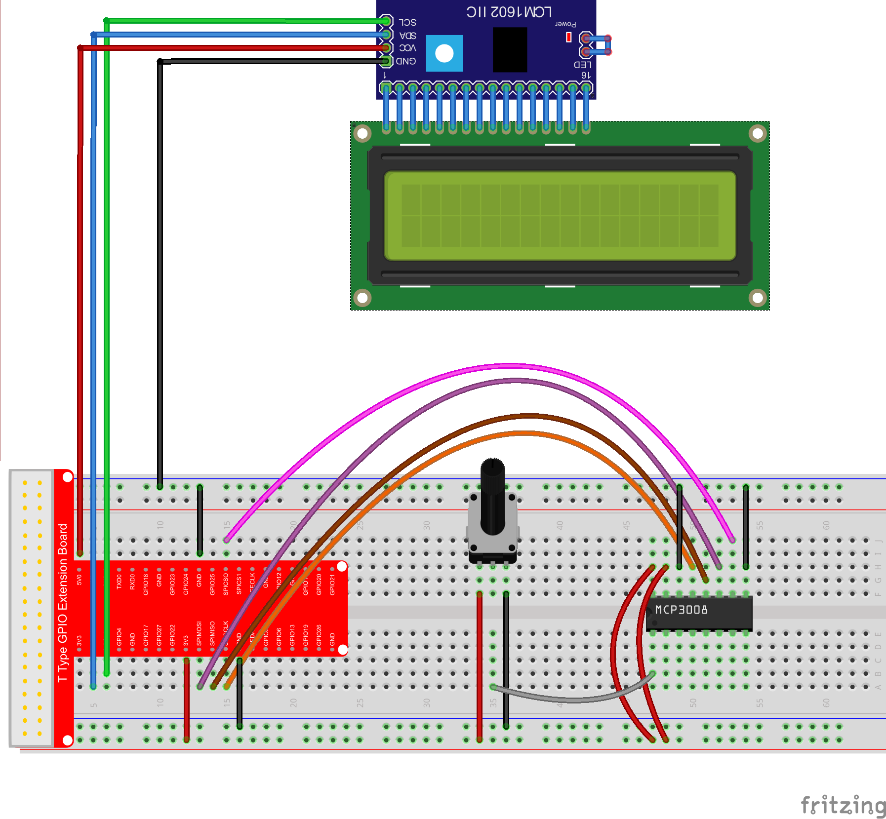
Hardware Setup
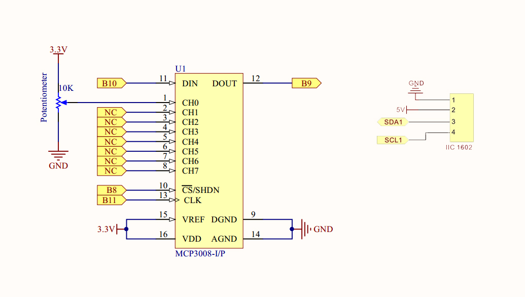
In this project, we’ll wire up the Pi with an external MCP3008 ADC, and measure the analog value via that. Then display the voltage value on 1602 LCD,The schematic as shown below:
Sample code
Regarding how to enable SPI and I2C, please read lesson10 and lesson13
for C language user
1) Download the C sample code by typing following command in terminal: cd ~
If you want to customize the sample code file , you can use nano editor to edit source code by typing following command: sudo nano voltmeter.c
2) Compile code
gcc -Wall -o voltmeter voltmeter.c -lwiringPi
3) Run the program
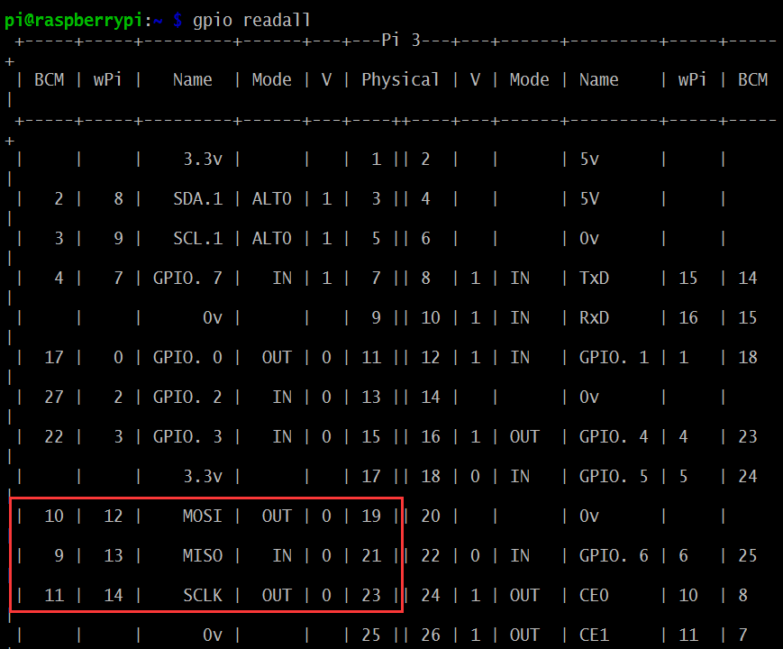
Before running program, please run command gpio readall to check whether MOSI、MISO、SCLK(B10、B9、B11) works as alternative functions, If the terminal shows as following: Please run the following command to change as alternative functions
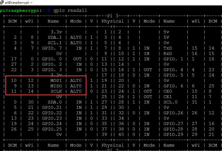
If the terminal shows as the following, please go on running program
sudo ./voltmeter
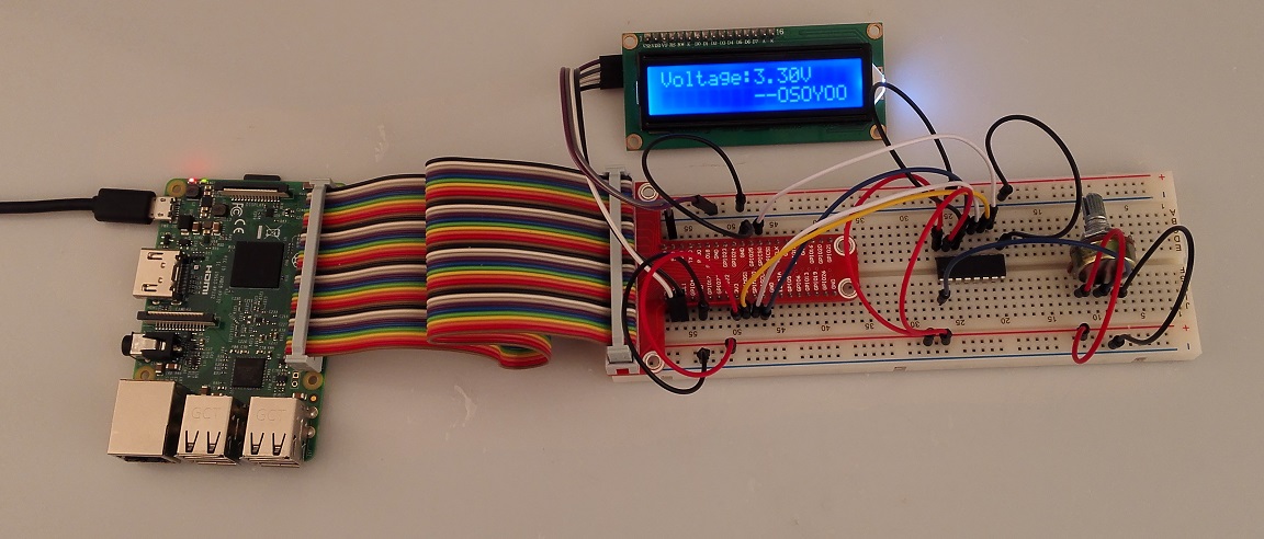
4) Running result
Once you run the program,the terminal will show print message as code firstly. the 1602 lcd will display the Potentiometer voltage, rotate the shaft of the potentiometer to adjust voltage between 0-3.3V.
C language Code Analysis
#include < stdint.h>
#include < string.h>
#include < errno.h>
#include < wiringPi.h>
#include < stdio.h>
#include < stdlib.h>
#include < wiringPiSPI.h>
#include < wiringPiI2C.h>

#define LCDADDR             0x3F //IIC LCD address
#define BLEN                1   //1--open backlight,0--close backlight

#define CHAN_CONFIG_SINGLE  8   //setup channel 0 as Single-ended input
#define SPICHANNEL          0   //MCP3008 connect to SPI0
#define ANALOGCHANNEL       0   //Potentiometer connect MCP3008 analog channel 0

static int spifd ;
static int i2cfd;

void spiSetup (int spiChannel)
{
    if ((spifd = wiringPiSPISetup (spiChannel, 10000)) < 0)
    {
        fprintf (stderr, "Can't open the SPI bus: %s\n", strerror (errno)) ;
        exit (EXIT_FAILURE) ;
    }
}

int myAnalogRead(int spiChannel,int channelConfig,int analogChannel)
{
    if(analogChannel7)
        return -1;
    unsigned char buffer[3] = {1}; // start bit
    buffer[1] = (channelConfig+analogChannel) << 4;
    wiringPiSPIDataRW(spiChannel, buffer, 3);
    return ( (buffer[1] & 3 ) << 8 ) + buffer[2]; // get last 10 bits
}

void print_info()
{
    printf("\n");
    printf("|************************************|\n");
    printf("|                 Voltemter          |\n");
    printf("|       -------------------------    |\n");
    printf("|       | ADC |           | Pi  |    |\n");
    printf("|       |-----|-----------|-----|    |\n");
    printf("|       | CS  | connect to| CE0 |    |\n");
    printf("|       | Din | connect to| MOSI|    |\n");
    printf("|       | Dout| connect to| MISO|    |\n");
    printf("|       | CLK | connect to| SCLK|    |\n");
    printf("|       | CH0 | connect to| 3.3V|    |\n");
    printf("|       | CH1 | connect to| GND |    |\n");
    printf("|************************************|\n");
    printf("|   Potentiometer connect to ADC CH0 |\n");
    printf("|                              OSOYOO|\n");
    printf("|************************************|\n");
    printf("\n");

}

//write a word to lcd
void write_word(int data){
    int temp = data;
    if ( BLEN == 1 )
        temp |= 0x08;
    else
        temp &= 0xF7;
    wiringPiI2CWrite(i2cfd, temp);
}

//send command to lcd
void send_command(int comm){
    int buf;
    // Send bit7-4 firstly
    buf = comm & 0xF0;
    buf |= 0x04;            // RS = 0, RW = 0, EN = 1
    write_word(buf);
    delay(2);
    buf &= 0xFB;            // Make EN = 0
    write_word(buf);

    // Send bit3-0 secondly
    buf = (comm & 0x0F) << 4;
    buf |= 0x04;            // RS = 0, RW = 0, EN = 1
    write_word(buf);
    delay(2);
    buf &= 0xFB;            // Make EN = 0
    write_word(buf);
}

//send data to lcd
void send_data(int data){
    int buf;
    // Send bit7-4 firstly
    buf = data & 0xF0;
    buf |= 0x05;            // RS = 1, RW = 0, EN = 1
    write_word(buf);
    delay(2);
    buf &= 0xFB;            // Make EN = 0
    write_word(buf);

    // Send bit3-0 secondly
    buf = (data & 0x0F) << 4;
    buf |= 0x05;            // RS = 1, RW = 0, EN = 1
    write_word(buf);
    delay(2);
    buf &= 0xFB;            // Make EN = 0
    write_word(buf);
}

//initialize the lcd
void init(){
    send_command(0x33); // Must initialize to 8-line mode at first
    delay(5);
    send_command(0x32); // Then initialize to 4-line mode
    delay(5);
    send_command(0x28); // 2 Lines & 5*7 dots
    delay(5);
    send_command(0x0C); // Enable display without cursor
    delay(5);
    send_command(0x01); // Clear Screen
    wiringPiI2CWrite(i2cfd, 0x08);
}

//clear screen
void clear(){
    send_command(0x01); //clear Screen
}

//Print the message on the lcd
void write(int x, int y, char data[]){
    int addr, i;
    int tmp;
    if (x < 0) x = 0; if (x > 15) x = 15;
    if (y < 0) y = 0; if (y > 1)  y = 1;

    // Move cursor
    addr = 0x80 + 0x40 * y + x;
    send_command(addr);

    tmp = strlen(data);
    for (i = 0; i < tmp; i++){
        send_data(data[i]);
    }
}

int main()
{
    int adc;
    float voltage;
    char buf[5];
    if(wiringPiSetup() < 0)
    {   fprintf(stderr,"Can't init wiringPi: %s\n",strerror(errno));
        exit(EXIT_FAILURE);
    }

    spiSetup(SPICHANNEL);//init spi

    i2cfd = wiringPiI2CSetup(LCDADDR);//init i2c
    init();//init LCD
    clear();//clear screen

    print_info();

    while(1)
    {
        adc = myAnalogRead(SPICHANNEL,CHAN_CONFIG_SINGLE,ANALOGCHANNEL);
        voltage = adc/1024.*3.3;
        write(0,0,"Voltage:");
        sprintf(buf,"%1.2f",voltage);//float change to string
        write(8,0,buf);//print voltage on lcd
        write(12,0,"V");//print unit

        write(8,1,"--OSOYOO");
        delay(1000);
    }
    return 0;
}
For python user, please take steps as following:
1) Download the python sample code by typing the command as followed:
If you want to customize the sample code file , you can use nano editor to edit source code by typing following command: sudo nano voltmeter.py
2) Run the program
sudo python ./voltmeter.py
3) Running result
Once you run the program,the terminal will show print message as code firstly. the 1602 lcd will display the Potentiometer voltage, rotate the shaft of the potentiometer to adjust voltage between 0-3.3V.
Python sample code Analysis
import time
import os
import RPi.GPIO as GPIO
import smbus

# Define some device parameters
I2C_ADDR  = 0x3F # I2C device address, if any error, change this address to 0x27
LCD_WIDTH = 16   # Maximum characters per line

# Define some device constants
LCD_CHR = 1 # Mode - Sending data
LCD_CMD = 0 # Mode - Sending command

LCD_LINE_1 = 0x80 # LCD RAM address for the 1st line
LCD_LINE_2 = 0xC0 # LCD RAM address for the 2nd line
LCD_LINE_3 = 0x94 # LCD RAM address for the 3rd line
LCD_LINE_4 = 0xD4 # LCD RAM address for the 4th line

LCD_BACKLIGHT  = 0x08  # On
#LCD_BACKLIGHT = 0x00  # Off

ENABLE = 0b00000100 # Enable bit
# Timing constants
E_PULSE = 0.0005
E_DELAY = 0.0005

# change these as desired - they're the pins connected from the
# SPI port on the ADC to the Cobbler
SPICLK = 11
SPIMISO = 9
SPIMOSI = 10
SPICS = 8
analogChannel = 0

#Open I2C interface
#bus = smbus.SMBus(0)  # Rev 1 Pi uses 0
bus = smbus.SMBus(1) # Rev 2 Pi uses 1

#setup function for some setup---custom function
def setup():
    #set the gpio modes to BCM numbering
    GPIO.setmode(GPIO.BCM)
    # set up the SPI interface pins
    GPIO.setup(SPIMOSI, GPIO.OUT)
    GPIO.setup(SPIMISO, GPIO.IN)
    GPIO.setup(SPICLK, GPIO.OUT)
    GPIO.setup(SPICS, GPIO.OUT)
    pass

def lcd_init():
  # Initialise display
  lcd_byte(0x33,LCD_CMD) # 110011 Initialise
  lcd_byte(0x32,LCD_CMD) # 110010 Initialise
  lcd_byte(0x06,LCD_CMD) # 000110 Cursor move direction
  lcd_byte(0x0C,LCD_CMD) # 001100 Display On,Cursor Off, Blink Off
  lcd_byte(0x28,LCD_CMD) # 101000 Data length, number of lines, font size
  lcd_byte(0x01,LCD_CMD) # 000001 Clear display
  time.sleep(E_DELAY)

def lcd_byte(bits, mode):
  # Send byte to data pins
  # bits = the data
  # mode = 1 for data
  #        0 for command
  bits_high = mode | (bits & 0xF0) | LCD_BACKLIGHT
  bits_low = mode | ((bits<<4) & 0xF0) | LCD_BACKLIGHT # High bits bus.write_byte(I2C_ADDR, bits_high) lcd_toggle_enable(bits_high) # Low bits bus.write_byte(I2C_ADDR, bits_low) lcd_toggle_enable(bits_low) def lcd_toggle_enable(bits): # Toggle enable time.sleep(E_DELAY) bus.write_byte(I2C_ADDR, (bits | ENABLE)) time.sleep(E_PULSE) bus.write_byte(I2C_ADDR,(bits & ~ENABLE)) time.sleep(E_DELAY) def lcd_string(message,line): # Send string to display message = message.ljust(LCD_WIDTH," ") lcd_byte(line, LCD_CMD) for i in range(LCD_WIDTH): lcd_byte(ord(message[i]),LCD_CHR) #print message at the begining ---custom function def print_message(): print ('|**********************************|') print ('| Voltmeter |') print ('| ------------------------- |') print ('| | ADC | | Pi | |') print ('| |-----|-----------|-----| |') print ('| | CS | connect to| CE0 | |') print ('| | Din | connect to| MOSI| |') print ('| | Dout| connect to| MISO| |') print ('| | CLK | connect to| SCLK| |') print ('| | CH0 | connect to| 3.3V| |') print ('| | CH1 | connect to| GND | |') print ('| ------------------------- |') print ('| Potentiometer connect to CH0 |') print ('| OSOYOO|') print ('|**********************************|\n') print ('Program is running...') print ('Please press Ctrl+C to end the program...') # read SPI data from MCP3008 chip, 8 possible adc's (0 thru 7) def readadc(adcnum, clockpin, mosipin, misopin, cspin): if ((adcnum > 7) or (adcnum < 0)):
                return -1
        GPIO.output(cspin, True)

        GPIO.output(clockpin, False)  # start clock low
        GPIO.output(cspin, False)     # bring CS low

        commandout = adcnum
        commandout |= 0x18  # start bit + single-ended bit
        commandout <<= 3    # we only need to send 5 bits here
        for i in range(5):
                if (commandout & 0x80):
                        GPIO.output(mosipin, True)
                else:
                        GPIO.output(mosipin, False)
                commandout <<= 1
                GPIO.output(clockpin, True)
                GPIO.output(clockpin, False)

        adcout = 0
        # read in one empty bit, one null bit and 10 ADC bits
        for i in range(12):
                GPIO.output(clockpin, True)
                GPIO.output(clockpin, False)
                adcout <<= 1 if (GPIO.input(misopin)): adcout |= 0x1 GPIO.output(cspin, True) adcout >>= 1       # first bit is 'null' so drop it
        return adcout

#main function
def main():
    #print info
    print_message()
    # Initialise display
    lcd_init()
    #clear screen
    lcd_byte(0x01, LCD_CMD)
    while True:
        adc = readadc(analogChannel, SPICLK, SPIMOSI, SPIMISO, SPICS)
        voltage = round((adc/1024.*3.3),2)
        voltage = str(voltage)     #float change to string
        lcd_string("Voltage:        <",LCD_LINE_1)
        lcd_string(voltage,LCD_LINE_2)
        time.sleep(1.5)

#define a destroy function for clean up everything after the script finished
def destroy():
    #release resource
    GPIO.cleanup()

#
# if run this script directly ,do:
if __name__ == '__main__':
    setup()
    try:
            main()
    #when 'Ctrl+C' is pressed,child program destroy() will be executed.
    except KeyboardInterrupt:
        destroy()
        pass
    #clear screen
    finally:
        lcd_byte(0x01, LCD_CMD)
I know about the potentiometer. But i am asking about the function to turn off the backlight from the python code. the backlight consumes too much battery so i need to put it to sleep for some time.


Where is the function to toggle the backlight on/off?
You can turn around the Potentiometer at the back of LCD to adjust LCD backlight
I know about the potentiometer. But i am asking about the function to turn off the backlight from the python code. the backlight consumes too much battery so i need to put it to sleep for some time.