CONTENT
objective
Accessories introduction
Module introduction and assembly
- GM37-3530 Motor and Hall speed
- GY-521Mpu6050 Module
- Bluetooth module
- Tb6612FNG drive module
- Last install of all modules
Balance car assembly
- Motor mounting bracket mounting
- Installation of motors, couplings and wheels
- Main control board module installation
- Battery box installation
- Frame installation
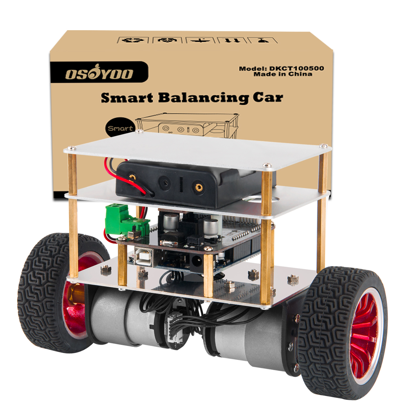
Objective
We introduce how to assemble a balance car and wiring in this lesson
Parts and Devices:
|
Device name
|
Picture |
Qty |
|
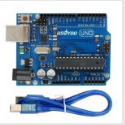
OSOYOO Basic Board for Arduino (fully compatiable with Arduino UNO R3)
|
 |
1
|
|
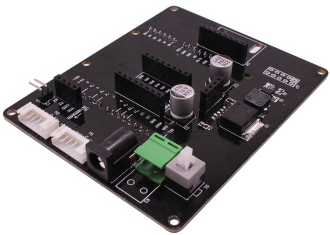
Expanding Board for Arduino
|
 |
1
|
|
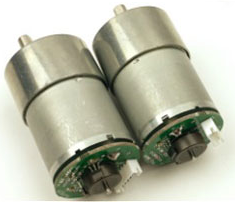
GM37-3530 Motor and Hall speed
|
 |
2
|
|
Tb6612FNG drive module
|
 |
1
|
|
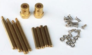
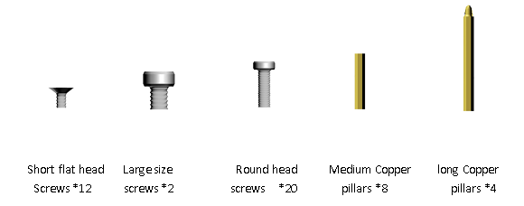
Screw and Nut
|
 |
1
|
|
Bluetooth module
|
 |
1
|
|
GY-521Mpu6050 Module
|
 |
1
|
|
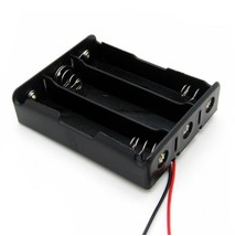
Box for 18650 3.7V battery
|
 |
1
|
|
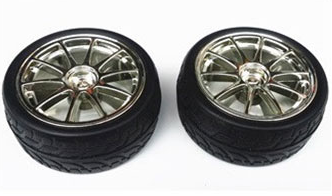
Wheel
|
 |
1
|
| Cable 6P*2 |
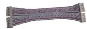 |
2
|
| Steel plate chassis |
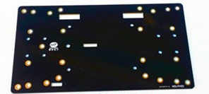 |
1
|
| Motor fixing bracket |
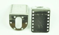 |
1
|
Accessories introduction
Module introduction and assembly
GM37-3530 Motor and Hall speed
We choose a motor with higher accuracy, To make the balance car PID control more sensitive and more easier to stand,Use Hall sensor measures motor speed
description:
1. Voltage: 12v
2. Speed: 10-1000RPM
3. Reduction ratio: 1 / 10-1 / 1000.
4. Shaft size can be customized
5. Transmission length: 37 mm
6. Direction: CW CCW
7. Long life, low noise
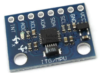
GY-521Mpu6050 Module
The MPU-6050 is a serious little piece of motion processing tech. By combining a MEMS 3-axis gyroscope and a 3-axis accelerometer on the same silicon die together with an onboard Digital Motion Processor™ (DMP™) capable of processing complex 9-axis MotionFusion algorithms, the MPU-6050 does away with the cross-axis alignment problems that can creep up on discrete parts. The breakout board for the MPU-6050 makes this tiny QFN package easy to work into your project. Every pin you need to get up and running is broken out to 0.1″ headers, including the auxiliary master I²C bus which allows the MPU-6050 to access external magnetometers and other sensors.You can visit the following link ,https://playground.arduino.cc/Main/MPU-6050
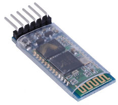
Bluetooth module
HC-06 Bluetooth module can reach a maximum transmission rate of 2.1M/s, support Bluetooth SPP Bluetooth serial protocol,http://www.instructables.com/id/Add-bluetooth-to-your-Arduino-project-ArduinoHC-06/
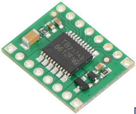
Tb6612FNG drive module
TB6612 is a dual drive that can drive two motors,control story and reverse by controlling the truth table of AIN1, AIN2, BIN1 and BIN2.http://forum.arduino.cc/index.php?topic=19395.0
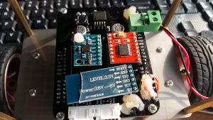
Last install of all modules
Note:pay attention to the connection of the power cord. Above the power terminal is connected to the red line VCC and the lower terminal is connected to the black line GND. If the connection is reversed, there will be a protection circuit inside the circuit that will not burn the circuit, but it will affect the performance of the entire circuit.
Balance car assembly
Motor mounting bracket mounting
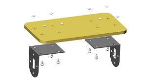
Operating instructions:Use eight round head screws to pass through motor bracket and plate and secure with nuts.
Installation of motors, couplings and wheels
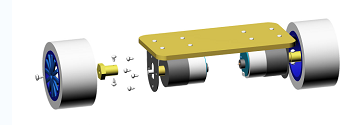
- Operating instructions:step1:The motor passes through the motor’s mounting bracket the shaft that near the top of the plate is secured with a short flat head screw.
- step2:Couplings are fitted with capless screws on the left and right sides and tightened with accessory tools.
- step3:One side of the hexagon is mounted on the corresponding hexagonal groove of the tire, and it is fixed with one large screw.
Main control board module installation
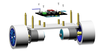
- Operating instructions:step1:Mount long copper posts in the four outermost mounting hole and fixed with round head screws.
- step2:The inside of the four mounting holes is installed in the copper column, using round head screws to fix.
- step3:The position of the copper pillar on the motherboard is fixed with round head screws.
Battery box installation
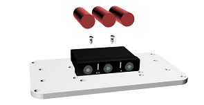
Operating instructions:Use two round head screws to pass through the two mounting holes of the battery box and Acrylic, then use the nuts to fix the back.
Frame installation
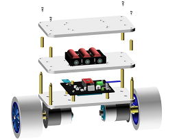
Operating instructions:The second layer of acrylic board passes through the bottom 4 long copper pillars, and is fixed with 4 middle copper pillars. The top floor acrylic board is installed in the corresponding second layer of 4 middle copper pillars and fixed with 4 round head screws.


