Introduction
The real time traffic light controller is a complex piece of equipment which consists of power cabinet, main controller or processor, relays, control panel with switches or keys, communication ports etc.
In this lesson, we will go over how to build a traffic light circuit with an Arduino microcontroller.
Preparations
HARDWARE
- Osoyoo UNO Board (Fully compatible with Arduino UNO rev.3) x 1
- One Digit 7-Segment LED Display x 1
- 74HC595 x 1
- 200 ohm Resistor x 7
- LEDs (Red LED x 2, Yellow LED x 2, Green LED x 2)
- Breadboard x 1
- Jumpers
- USB Cable x 1
- PC x 1
About this project
The use of personal vehicles is very common now a days and a result, the number of vehicles on the roads are exponentially increasing. Roads without any supervision or guidance can lead in to traffic congestions and accidents.
Traffic Lights or Traffic Signals are signalling devices that are used to control the flow of traffic. Generally, they are positioned at junctions, intersections, ‘X’ roads, pedestrian crossings etc. and alternate the priority of who has to wait and who has to go.
The traffic lights will provide instructions to the users (drivers and pedestrians) by displaying lights of standard color. The three colors used in traffic lights are Red, Yellow and Green.
In this project, an Arduino based Traffic Light Controller system is designed. It is a simple implementation of traffic lights system but can be extended to a real time system with programmable timings, pedestrian lighting etc. There is a green LED, which represents the green light. A yellow LED, which represents the yellow light. And a red LED, which represents the red light.
We will show all the hardware connections and the software needed to make this circuit work.
Connection
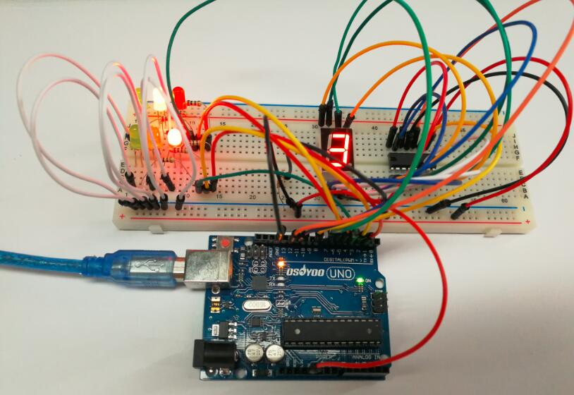
Build the circuit as below:

In this experiment, we use a 7-segment display to count down and set two groups of traffic lights to represent two directions, let’s say, north-south (TF1) and east-west (TF2), as shown in the above picture.
CODE PROGRAM
After above operations are completed, connect the Arduino board to your computer using the USB cable. The green power LED (labelled PWR) should go on.Open the Graphical Programming software Mixly and follow the next operations:
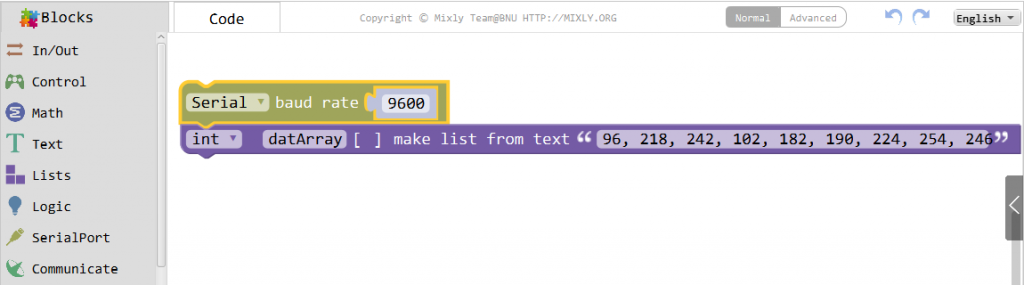
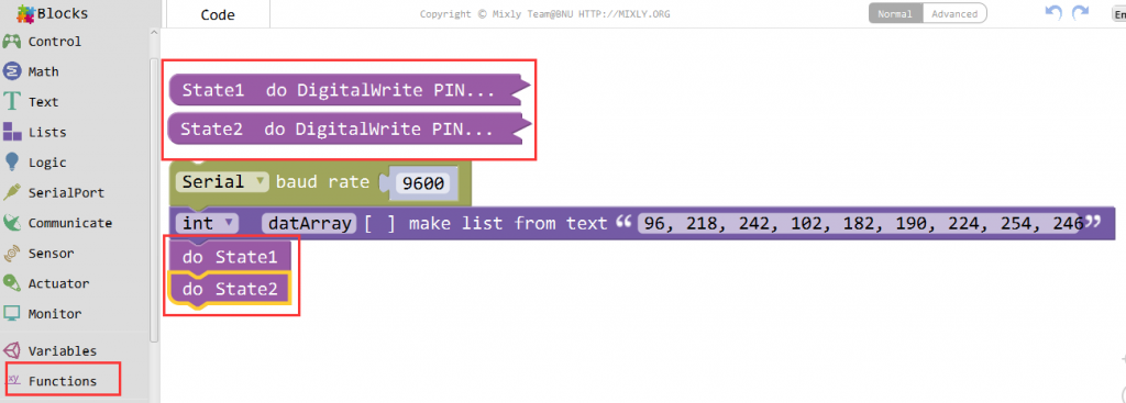
Setup baud rate and define datArray[] to store the to-be-display number.
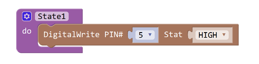
Set a function State 1(), to light up a red LED(Pin 5).
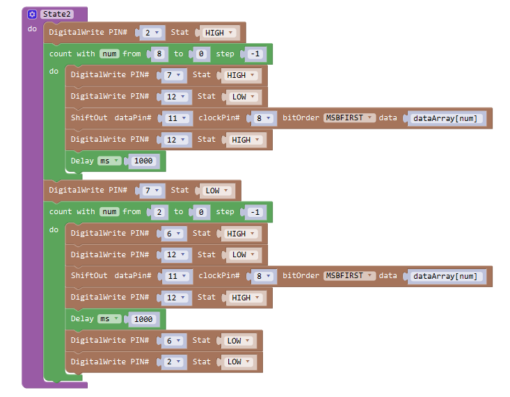
Display the number from 9 to 1 on the 7-segment Display, and light up the Green2 LED (Pin 4), set T_CP( Pin 12) Low and hold low for transmitting, then pull it to save the data.

Turn off the Green LED (Pin 4), and display the number 3 to 1 on the display, then turn on Yellow 2 LED (Pin 3). Next, dim LED Yellow 2 and Red 1( Pin 5).

Next comes the State2() The blocks of State2() is just similar and you can study by yourself.
Execute function State 1() and State2().
Running Result
A few seconds after the upload finishes, you can see what is similar to the traffic light now. First, the 7-segment display counts down from 9s, and the red light in the TF1 and the green one in the TF2 light up. Then it counts down from 3, and the green LED in the TF2 goes out when the yellow lights up, with the TF1 red light still on. 3s later, the 7-segment counts down from 9s again. Meanwhile, the red light in the TF2 and the green in the TF1 light up. After 9s, it counts down from 3s, when the yellow light in the TF1 lights up and the red in the TF2 keeps on. And this repeats over and over again, as a traffic light would.
Although it is not the ideal implementation for real life scenarios, it gives an idea of the process behind the traffic light control system.
Note: The project implemented here doesn’t include the pedestrian crossing and pedestrian signaling in to consideration.
Once you know how the software operates, you can change the values to make the LEDs be on or off for any period of time. For example, instead of being on for 9 seconds, you can easily change it to 15 seconds or 30 seconds. You could make the yellow LED be on just for 1 second or 2 seconds.


