INTRODUCTION
IR, or infrared, communication is a common, inexpensive, and easy to use wireless communication technology. IR light is very similar to visible light, except that it has a slightlty longer wavelength. This means IR is undetectable to the human eye – perfect for wireless communication. For example, when you hit a button on your TV remote, an IR LED repeatedly turns on and off, 38,000 time a second, to transmit information (like volume or channel control) to an IR photo sensor on your TV.
This tutorial will first explain the inner workings of common IR communication protocols. Then we will go over three examples that will allow you to transmit and receive IR data using an Arduino. In this example, we will read incoming IR data from a common remote control using the 1838B IR photo sensor.
Preparations
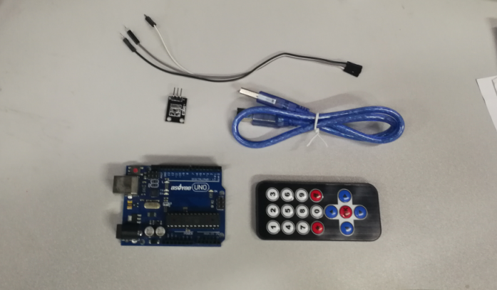
HARDWARE
- Osoyoo UNO Board (Fully compatible with Arduino UNO rev.3) x 1
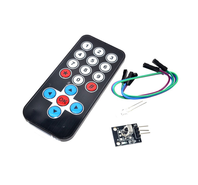
- Infrared Receiver x 1
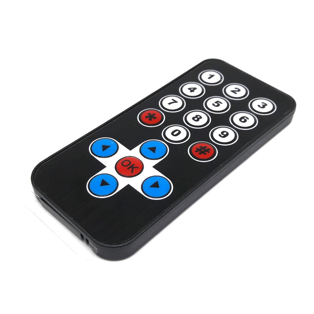
- Remote Controller x 1
- Jumpers
- USB Cable x 1
- PC x 1
About the IR
WHAT IS IR?
Infra-Red light is actually normal light with a particular colour. We humans can’t see this colour because its wave length of about 950nm is below the visible spectrum. That’s one of the reasons why IR is chosen for remote control purposes, we want to use it but we’re not interested in seeing it. Another reason is because IR LEDs are quite easy to make, and therefore can be very cheap, thus making it ideal for us hobbyists to use IR control for our own projects.
We need to konw there are many more sources of Infra-Red light. The sun is the brightest source of all, but there are many others, like: light bulbs, candles, central heating system, and even our body radiates Infra-Red light.
A common modulation scheme for IR communication is something called 38kHz modulation. There are very few natural sources that have the regularity of a 38kHz signal, so an IR transmitter sending data at that frequency would stand out among the ambient IR. 38kHz modulated IR data is the most common, but other frequencies can be used.
When you hit a key on your remote, the transmitting IR LED will blink very quickly for a fraction of a second, transmitting encoded data to your appliance.
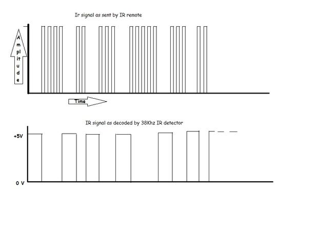
If you were to hook an oscilloscope up to your TV remote’s IR LED, you would see a signal similar to the one above. This modulated signal is exactly what the receiving system sees. However, the point of the receiving device is to demodulate the signal and output a binary waveform that can be read by a microcontroller. When you read the OUT pin of the VS1838B with the wave from above, you will see something like the second.
Modulation
As everything that radiates heat, also radiates Infra-Red light. Therefore we have to take some precautions to guarantee that our IR message gets across to the receiver without errors.Modulation of the signal on a carrier frequency is the answer to make our signal stand out above the noise. With modulation we make the IR light source blink in a particular frequency. The IR receiver will be tuned to that frequency, so it can ignore everything else.
In the picture below you can see a modulated signal driving the IR LED of the transmitter on the left side. The detected signal is coming out of the receiver at the other side.
(Thanks to SBProjects.com for the gif and excellent IR resource!)
TECHNICAL DETAILS OF VS1838B IR RECEIVER
- Model Number : VS1838B;
- Working Voltage :2.7V to 5.5V
- Reception Distance : 18M;
- Reception Angle : ± 45 Degree;
- Low Level Voltage : 0.4V
- High Level Voltage : 4.5V;
- Body Size : 7 x 7 x 5mm / 0.27″ x 0.27″ x 0.2″(L*W*T);
- Pin Length : 22.5mm / 0.88″
- Pitch : 2mm / 0.08″;
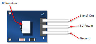
THE PINOUT FOR VS1838B IR RECEIVER:
ABOUT THE IR CONTROL

Infrared remotes are still the cheapest way to wirelessly control a device. We have designed the remote to be small, very simple, and low-cost.There are many different IR remote controls. all of these may have different encoding methods and number of physical buttons, and different codes received when a button is pressed.
Examples
READ CODES FROM IR REMOTE
This example will show you how to read IR remote codes from any IR remote using the VS1838B IR receiver and an Arduino. Once you can receive codes from individual button presses, your remote control and Arduino become a general purpose, short range, communication interface!
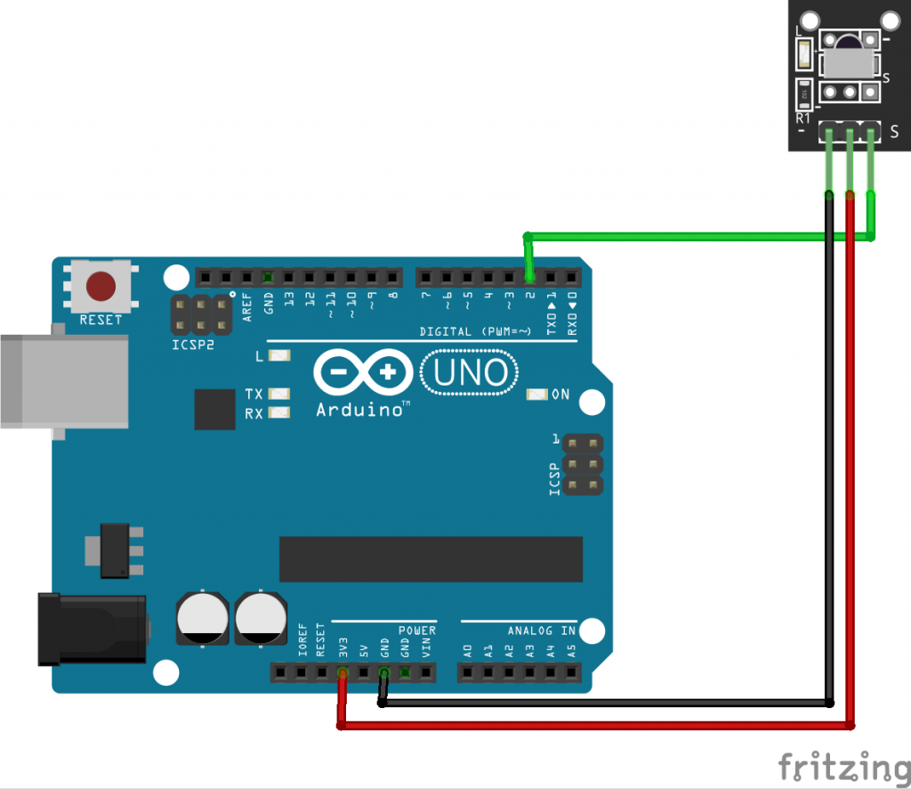
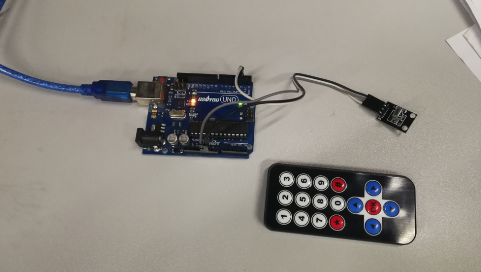
Connection
Build the circuit as below:
CODE PROGRAM
After above operations are completed, connect the Arduino board to your computer using the USB cable. The green power LED (labelled PWR) should go on.Open the Graphical Programming software Mixly and follow the next operations:
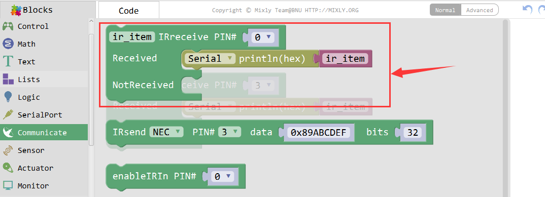
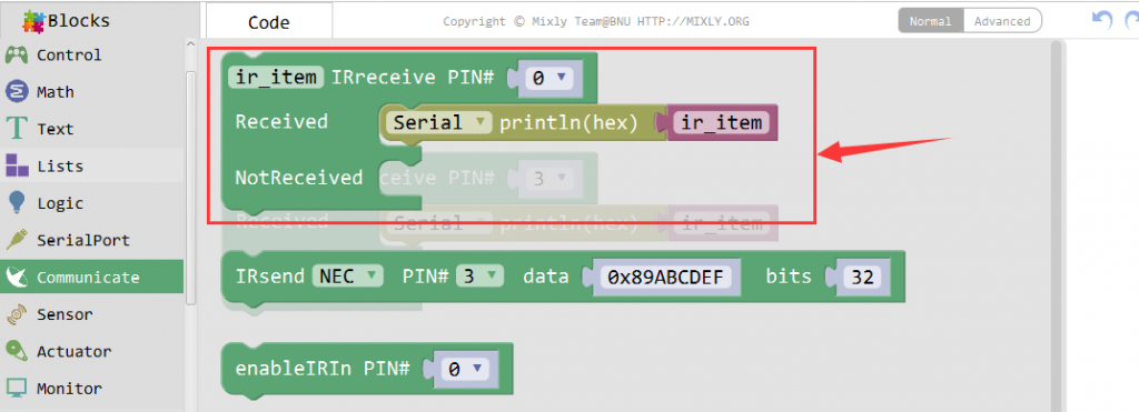
Drag out the IR Control block from the Communications.
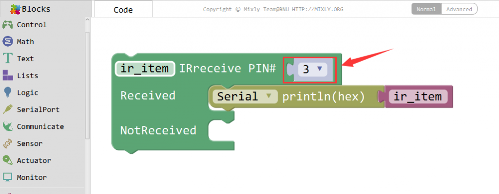
Connect the IRreceive PIN to D3.
Click Save aftogramming is done. Select the board type and serial port before uploading. For instause a Uno board, just select Arduino/Genuino Uno: if you use a Mega2560, select Arduino/Genuino Mega or Mega2560. 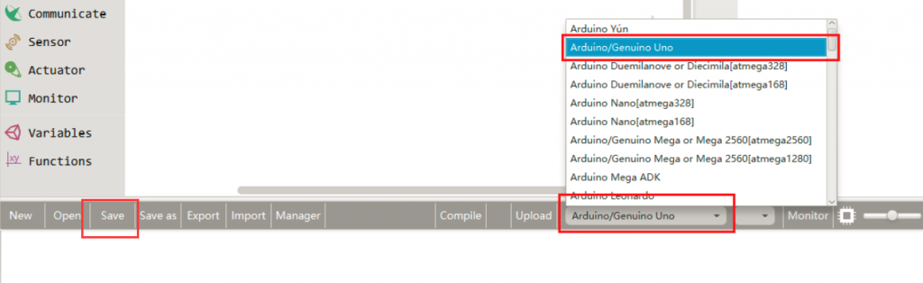
Select the serial device of the Arduino board from the COM menu. This is likely to be COM3 or higher (COM1 and COM2 are usually reserved for hardware serial ports). To find out, you can disconnect your Arduino board and re-open the menu; the entry that disappears should be the Arduino board. Reconnect the board and select that serial port.

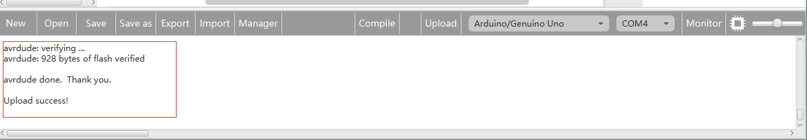
Next,upload the code. If the uploading fails, check and correct the code according to the prompts.


Finally, the staus will change to ‘Upload success!’.

Running Result
The sketch will automatically decode the type of remote you are using and identify which button on your remote is pressed. Open the Serial Monitor in the Mixly at 9600 bps and hit different buttons on your remote.
The Serial Monitor displaying random button presses on my remote. Different buttons show different codes:
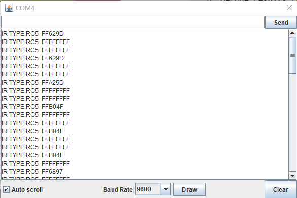
If you use the sketch above and count the 17 buttons from left to right and top to bottom, the codes received are these: (NOTE: Receiving “FFFFFFFF” means “repeat” if you hold the button down.)
| 1 |
FFA25D |
| 2 |
FF629D |
| 3 |
FFE21D |
| 4 |
FF22DD |
| 5 |
FF02FD |
| 6 |
FFC23D |
| 7 |
FFE01F |
| 8 |
FFA857 |
| 9 |
FF906F |
| 10 |
FF6897 |
| 11 |
FF9867 |
| 12 |
FFB04F |
| 13 |
FF18E7 |
| 14 |
FF10EF |
| 15 |
FF38C7 |
| 16 |
FF5AA5 |
| 17 |
FF4AB5 |