In last lesson, we’ve learned how to control a single LED using Raspberry Pi. Now let’s make the project a little bit more complex: Using Raspberry pi to control eight LEDs and make them blink in sequence.
Software Preparation Note: In this lesson, we remotely control raspberry pi via PuTTy on PC. To learn how to config raspberry pi, please visit lesson 1: getting started with raspberry pi.
Experimental Principle
LED(light-emitting diode) is a two-lead semiconductor light source. It is a p-n junction diode that emits light when activated.When a suitable voltage is applied to the leads, electrons are able to recombine with electron holes within the device, releasing energy in the form of photons. This effect is called electroluminescence, and the color of the light (corresponding to the energy of the photon) is determined by the energy band gap of the semiconductor.
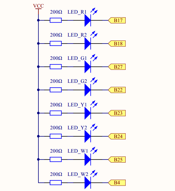
Connect the eight LEDs(positive electrode) to Resistor (200Ω) to limit the current, negative electrode to B17, B18, B28, B22, B23, B24, B25, B4 respectively. B means BCM(Broadcom pin number). If you don’t know what is BCM pin#, please review our lesson 3: Introduction Of Raspberry Pi GPIO .
The resistor has been connected to the 3.3V power supply, if the low voltage(oV) is applied to negative electrode, the LED will light up. The schematic diagram as shown below:
Step 1: Hardware Setup
Assembling the circuit as followed Connection Graph
Step 2:Software
we’ll provide two kinds of codes for C language users and Python language users.
For C Language users, please take following steps:
Firstly, Please make sure the wiringPi library is installed, if you don’t know how to install it, please visit: https://osoyoo.com/?p=7027
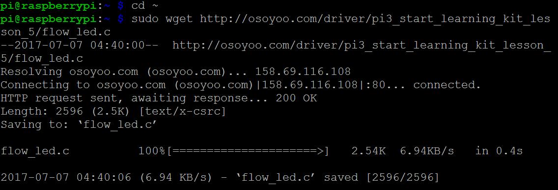
1) Download the C sample code flow_led.c from osoyoo by typing following command: cd ~ sudo wget http://osoyoo.com/driver/pi3_start_learning_kit_lesson_5/flow_led.c
Note: sudo means to run with the permission of superuser; wget stands for “web get” and means to download files over a network. sudo wget http://osoyoo.com/driver/flow_led.c is to download folw_led.c file from osoyoo to your pi with the permission of superuser.
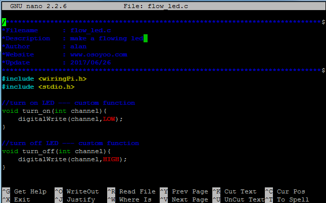
If you want to customize the sample code file , you can use nano editor to edit source code by typing following command in terminal: sudo nano flow_led.c
Then you will go to flow_led.c file, then copy the code to there, press Ctrl+X to Exit andtype “Y” to save the file.
4) Compile Code
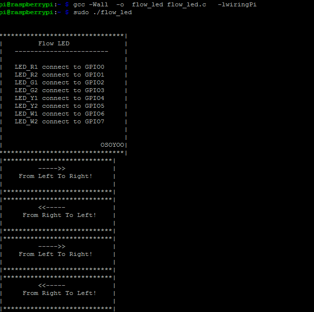
C language is high level language. Before running the project, the code need to compile as an executable file. Please enter the following command: gcc -Wall -o flow_led flow_led.c -lwiringPi Note: gcc: is GNU Compiler Collection. If you want to write your own C code and compile to run it, you need to master gcc. for more information about gcc, please visit here -Wall: to get more error when compile the code -o: to name the compiled file. You can name the file as your like. here we name as flow_led flow_led.c: means the original file which is compiled -lwiringPi: is to load the library wiringPi (l is short for library)
5) Run the Program
Enter the following command and press “enter” to run the project: sudo ./flow_led
6) Running result
Once run the program, the LED will blink from left to right, then reverse from right to left in sequence. If you wan’t to stop the program, please go to terminal and type command: Ctrl + C, press “Enter” to stop it. As we mentioned you can use nano to edit the code, so next we give details explanation about the code as following so that you can understand the code fully and try to modify the above code to personalize it or change the way the LEDs are chosen or lit.
C language Code Analysis
#include < wiringPi.h>
#include < stdio.h>
a) Add header file(.h file) which is used in this project at the beginning of the code. Note: WiringPi is a GPIO interface library for the Raspberry Pi, it includes a command-line utility gpio which can be used to program and setup the GPIO pins. You can use this to read and write the pins and even use it to control them from shell scripts.
Stdio is a system I/O library for C, In C/C++ . I /O functions such as printf(), scanf(), cout,cin belong to Stdio library. So you need include head file in order to use these I/O functions.
//turn on LED --- custom function
void turn_on(int channel){
    digitalWrite(channel,LOW);
}

//turn off LED --- custom function
void turn_off(int channel){
    digitalWrite(channel,HIGH);
}
These two custom function above defined to turn on/off the LED. here we use the function in WiringPi Library, for more details regarding wiringPi and API, please visit:
 void setup(){
    int i;
    for(i=0;i<8;i++){
        pinMode(i,OUTPUT); //i is the wiringPi GPIO code
        digitalWrite(i,HIGH);//i is the wiringPi GPIO code

    }
}
Above statement configure the GPIO to BCM numbering scheme and set pins to output mode, set the initial level as high level (3.3V). The variable i in pinMode(i, OUTPUT) and digitalWrite(i,HIGH) function means the wiringPi GPIO pin code. i=0 means wiringPi pin0 or BCM17 , i=1 means wiringPi #1 or BCM#18… , for detail about wiringPi pin# and BCM pin# relation, please read our lesson 2 Introduction Of Raspberry Pi GPIO .
 int main(){
    int i;
    if(wiringPiSetup()==-1){
        printf("setup wiringPi failed!\n");
        printf("please check your setup\n");
        return -1;
    }

    setup();
    printf("\n");
    printf("\n");
    printf("********************************|\n");
    printf("|         Flow LED              |\n");
    printf("|   ------------------------    |\n");
    printf("|                               |\n");
    printf("|   LED_R1 connect to GPIO0     |\n");
    printf("|   LED_R2 connect to GPIO1     |\n");
    printf("|   LED_G1 connect to GPIO2     |\n");
    printf("|   LED_G2 connect to GPIO3     |\n");
    printf("|   LED_Y1 connect to GPIO4     |\n");
    printf("|   LED_Y2 connect to GPIO5     |\n");
    printf("|   LED_W1 connect to GPIO6     |\n");
    printf("|   LED_W2 connect to GPIO7     |\n");
    printf("|                               |\n");
    printf("|                               |\n");
    printf("|                         OSOYOO|\n");
    printf("********************************|\n");

    while(1){
        //turn led from left to right
        printf("|****************************|\n");
        printf("|         ----->>            |\n");
        printf("|    From Left To Right!     |\n");
        printf("|                            |\n");
        printf("|****************************|\n");
        for(i=0;i<8;i++){
            turn_on(i);
            delay(150);
            turn_off(i);
        }
        //turn on from righ to left
        printf("|****************************|\n");
        printf("|         <); printf("| From Right To Left! |\n"); printf("| |\n"); printf("|****************************|\n"); for(i=7;i>=0;i--){
            turn_on(i);
            delay(150);
            turn_off(i);
        }
    }
    return 0;
}
Main function main() is a program shall contain a global function named main, which is the designated start of the program. Main function main() invokes setup()function to initialize the GPIO, then print the formatted output onto the screen. while() function to set the LED blink from left to right then reverse from right to left in sequence.
For Python Language users, please follow the below step:
If your Raspberry Pi is connected with a Monitor through HDMI cable,then you can program in Python 3(IDLE) GUI environment directly,for more details please visit: https://osoyoo.com/2017/06/23/python-light-led/
In this example, we use command line to remote access Pi through ssh client Putty. 1) Download the Python Sample code from osoyoo by typing following command: cd ~
If you want to customize the sample code file , you can use nano editor to edit source code by typing following command in terminal:
sudo nano flow_led.py
Note: cd means to change to the intended directory from the current path. Informally,cd ~ is to go to the path /home/pi/, Nano is an editor. flow_led.py is the file name, you can name the file as you like.
Then copy the code from here , then paste the code to file as above photo, press Ctrl+X to Exit andtype “Y” to save the file.
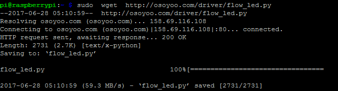
Note: sudo means to run with the permission of superuser; wget stands for “web get” and means to download files over a network. sudo wget http://osoyoo.com/driver/flow_led.py is to download folw_led.py file from osoyoo to your pi with the permission of superuser.
3) Run the Program
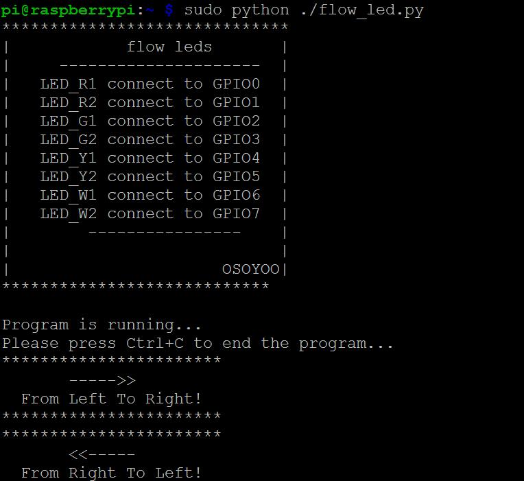
Enter the following command and press “enter” to run the project: sudo python ./flow_led.py
4)Running Result
Once the program is running, the LED will blink from left to right, then reverse from right to left in sequence.
Python language Code Analysis
importRPi.GPIOasGPIO importtime
Import Python GPIO Library and time library. The GPIO library is the library for interacting with the GPIO in Python. It does the job of simplifying the process. The time library is there so we can put a delay in, otherwise the blink might be too fast to notice.
Set 8 pins for LEDs, here use LedPins() to define the GPIO Pins,LedPins is list name. for more information about list,please visit here. From the list we can see there are eight LEDs connect to 17, 18, 22,23, 24, 25,4 respectly (We configure the GPIO to use the Broadcom numbering system)
#print message at the begining ---custom function
def print_message():
    print ('******************************')
    print ('|            flow leds       |')
    print ('|     ---------------------  |')
    print ('|   LED_R1 connect to GPIO0  |')
    print ('|   LED_R2 connect to GPIO1  |')
    print ('|   LED_G1 connect to GPIO2  |')
    print ('|   LED_G2 connect to GPIO3  |')
    print ('|   LED_Y1 connect to GPIO4  |')
    print ('|   LED_Y2 connect to GPIO5  |')
    print ('|   LED_W1 connect to GPIO6  |')
    print ('|   LED_W2 connect to GPIO7  |')
    print ('|        ----------------    |')
    print ('|                            |')
    print ('|                      OSOYOO|')
    print ('****************************\n')
    print ('Program is running...')
    print ('Please press Ctrl+C to end the program...')

Define a function to print the LED and GPIO connection. regarding how to define a function, please visi here

#setup function for some setup---custom function
def setup():
    GPIO.setwarnings(False)
    #set the gpio modes to BCM numbering
    GPIO.setmode(GPIO.BCM)
    #set all LedPin's mode to output,and initial level to HIGH(3.3V)
    GPIO.setup(LedPins,GPIO.OUT,initial=GPIO.HIGH)
Here we use some RPI.GPIO function: GPIO.setwarnings(False) is to disable false warningGPIO.setmode(GPIO.BCM) is to set the GPIO port to BCM number; GPIO.setup(LedPins,GPIO.OUT,initial=GPIO.HIGH) is to set the eight GPIO port to output mode, and the innitial level is HIGH LEVEL. for more information about RPI.GPIO function, please visi here
 def main():
    #print info
    print_message()
    while True:
        #turn LED on from left to right
        print("***********************")
        print("       ----->>         ")
        print("  From Left To Right!  ")
        print("***********************")
        for pin in LedPins:
            GPIO.output(pin,GPIO.LOW)
            time.sleep(0.2)
            GPIO.output(pin,GPIO.HIGH)
            pass

        #turn LED on from right to left
        print("***********************")
        print("       <)
        print("  From Right To Left!  ")
        print("***********************")
        for pin in reversed(LedPins):
            GPIO.output(pin,GPIO.LOW)
            time.sleep(0.2)
            GPIO.output(pin,GPIO.HIGH)
Main function main() invokes print_message() function first to print message onto the screen. in while loop use The for statement to set the LED blink from left to right in sequence then reverse() to make the LEDs blink from right to left. for more information about the reversed() please visit here


Connection (above breadboard to RPI) to the RPI 3 B+ is incorrect. Raspberry 3 B+, the pin 1(Red wire) is NOT on the USB side(showed above picture).
Raspberry 3 B+ PIN 1 on the opposite side of the USB side.
I hope that you will correct it..
Refer GPI pin details –
https://www.raspberrypi.org/documentation/usage/gpio/
https://pinout.xyz/
Thanks!
Sample code cannot be downloaded from raspberry pie. Is there any way?
hi, kimmusu ,
can you tell us which link you can not download the sample code?
Thank you for your quick reply.
It didn’t work yesterday, but I tried again today and it’s a good download.
I’m sorry to have bothered you.