Content
- Introduction
- Preparations
- About the Rotary Encoder
- Examples
Introduction
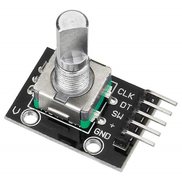
Rotary encoders are becoming more and more popular in consumer eletronics especially as control knobs in addition to their many other application areas. They are taking the place of potentiometers and navigation buttons where fast navigation, adjustment, data entry, and selection are reqired. Some encoders also include a built-in pushbutton which generates additional input to the processor which can be used as another user command in the control loop. You can see a typical incremental rotary encoder with push-on button on the picture below.
In this lesson, we will show how a rotary encoder works and how to use it with the Osoyoo UNO board.
Preparations
Hardware
- Osoyoo UNO Board (Fully compatible with Arduino UNO rev.3) x 1
- Rotary Encoder x 1
- I2C LCD 1602 Display x 1
- F/M jumpers
- USB Cable x 1
- PC x 1
Software
About the Rotary Encoder
Overview
A rotary encoder is a electro-mechanical device which converts rotational motion into digital or analog information. It looks very much like a potentiometer but it can turn in either clockwise or counter-clockwise direction infinitely.There are several types of rotary encoders. Absolute and relative (incremental) encoders are the two main types.While an absolute encoder outputs a value proportional to the current shaft angle, an incremental encoder outputs the step of the shaft and its direction.
SPECIFICATIONS:
- Flat top
- Push-button capability
- Pulses per rotation: 20
- Unlimited Rotations
- Pins are right-angle to the knob, but you can connect them to a breadboard using male-female jumper wires
- Standard pin spacing: 2.54mm (0.1″)
- Dimensions (exluding pins): 26.2mm (1.03″) length x 18.5mm (0.73″) width x 28.5mm (1.12″) height
- Total Shaft Dimensions: 20mm (0.79″) height x 6mm (0.24″) diameter
- Turning Portion of Shaft Dimensions: 12.5mm (0.49″) height x 6mm (0.24″) diameter
- Weight: 6.43g (0.23oz)
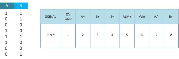
Pin Outs
The pin outs for this rotary encoder are identified in the illustration below.
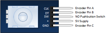
The module is designed so that a low is output when the switches are closed and a high when the switches are open.
The low is generated by placing a ground at Pin C and passing it to the CLK and DT pins when switches are closed.
The high is generated with a 5V supply input and pullup resistors, such that CLK and DT are both high when switches are open.
Not previously mentioned is the existence of of push button switch that is integral to the encoder. If you push on the shaft, a normally open switch will close. The feature is useful if you want to change switch function. For example, you may wish to have the ability to between coarse and fine adjustments.
Working Principle
In this tutorial we will going to test and wire the rotary encoder. Rotary encoder can be counted in the positive direction and the reverse direction during the rotation of the output pulse frequency and the rotation is continuous. Compare to rotary potentiometer this device has a limited rotation. The rotary encoder has its own push button built-in into the device itself, with the press of the button the encoder can be reset to its initial state, that start counting from 0 (ZERO).
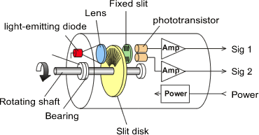
The incremental encoder is a displacement of the rotary pulse signal when it’s converted to series of digital rotating sensor. These pulse are used to control angular displacement. The angular displacement encoder conversion using photoelectric scanning principle. Reading the system of alternating light transmission window and the windows is not consisting of radial indexing plate rotating basis, when the infrared light source vertical irradiation light to the code disk image into the receiving.
At the surface the receiver is covered with diffraction grating, which has the same code disk window width. The receiver task is to feel the rotation of the disk creating a changes into the corresponding light electrical change and the low level signal up to a high level, along with the generation of square pulse, which must be processed by electric circuit. Reading the system typically employ a differential manner, and which the same but the phase is different of the two waveform by 180 degree compare to the signal in order to improve the stability of the output signal, reading should be formed on the basis to eliminate the interference.
The incremental encoders produce a series of pulses. These pulse are used to measure the rotation, position of the shaft, and velocity. There are two channel of rotary encoder output (A and B in US terminology). The encoder signals are offset from one another by ½ of a pulse. Sometimes this is also referred to a 90 degree phase separation. This term comes from discussing one entire encoder pulse cycle, from when the signal first rises up, to where it rises up again as 360 degrees. Then you can see that the distance of ½ of encoder pulse would be considered 90 degrees.
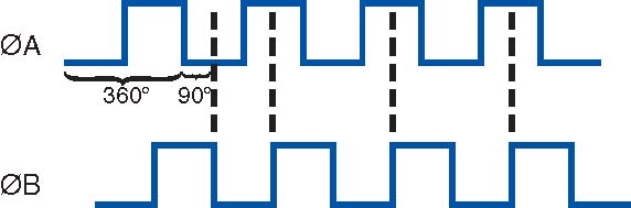
As you can see the illustration above there are two quadrature channel, and separated by 90 degrees, the user of the rotary encoder often wants to know the direction of rotation. Encoder manufacturers publish their specification for which signal comes first by specifying the direction of rotation.
The incremental encoders has two phase the square wave the phase difference between 90 degree, often referred as A and B channel. One of the channel is providing a speed related information at the same time by sequentially comparing two channel signals, the direction of rotation and the information obtained. There is also special signal called Z or ZERO channel, which gives the absolute zero rotary position, the signal shows a square wave with the center line of channel A square wave coincide. Incremental encoder accuracy depends on the mechanical electrical two factors, these factors are (RASTER INDEXING ERROR), (DISC ECCENTRICITY), (BEARING ECCENTRICITY), To know how much electrical equivalent of the mechanical angle of 360 degrees can be calculated with the following formula below.

Inside the encoder there are two switches. Once switch connects pin A to pin C and the other switch connects pin B to C.
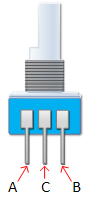
In each encoder position, both switches are either opened or closed. Each angular movement causes these switches to change states as follows:
- If both switches are closed, turning the encoder either clockwise or counterclockwise one position will cause both switches to open
- If both switches are open, turning the encoder either clockwise or counterclockwise one position will cause both switches to close.
The angular position of the A terminal and the B terminal is such that:
- Rotating the switch clockwise will cause the switch connecting A and C to change states first.
- Rotating the switch counterclockwise will cause the switch connecting B and C to change states first.
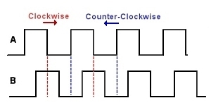
A & B Commutation Signals
Encoder indexing error is the electrical angle of the unit of two successive pulse maximum offset. Error exist in encoding which is caused by the aforementioned factors. The maximum error will be ± 25 electrical degrees (declared in any condition), equivalent to the rated offset value ± 7%, as the phase 90 degree electrical of two channels and the maximum deviation ± 35 electrical degrees is equal to ± 10% deviation left Ratings Right.
Examples
Use the Rotary Encoder with Arduino
In this lesson, we will show how to count the encoder position and how to determine direction of rotation.
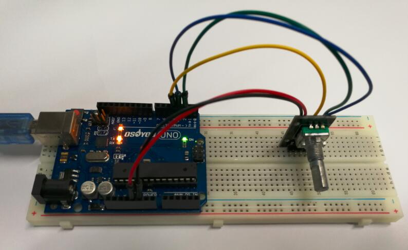
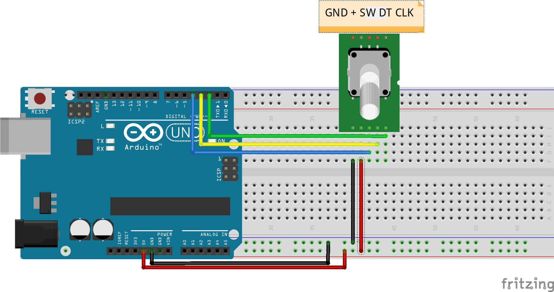
Connection
Build the circuit as below:
| Rotary Encoder |
Arduino |
| CLK |
D2 |
| DT |
D3 |
| + |
+5V |
| GND |
GND |
Code Program
After above operations are completed, connect the Arduino board to your computer using the USB cable. The green power LED (labelled PWR) should go on.Open the Arduino IDE and choose corresponding board type and port type for you project. Then load up the following sketch onto your Arduino.
const int clkPin= 2; //the clk attach to pin2 const int dtPin= 3; //the dt attach to pin3 const int swPin= 4 ;//the number of the button int encoderVal = 0; void setup() { //set clkPin,dePin,swPin as INPUT pinMode(clkPin, INPUT); pinMode(dtPin, INPUT); pinMode(swPin, INPUT); digitalWrite(swPin, HIGH); Serial.begin(9600); // initialize serial communications at 9600 bps } void loop() { int change = getEncoderTurn(); encoderVal = encoderVal + change; if(digitalRead(swPin) == LOW)//if button pull down { encoderVal = 0; } Serial.println(encoderVal); //print the encoderVal on the serial monitor } int getEncoderTurn(void) { static int oldA = HIGH; //set the oldA as HIGH static int oldB = HIGH; //set the oldB as HIGH int result = 0; int newA = digitalRead(dtPin);//read the value of clkPin to newA int newB = digitalRead(clkPin);//read the value of dtPin to newB if (newA != oldA || newB != oldB) //if the value of clkPin or the dtPin has changed { // something has changed if (oldA == HIGH && newA == LOW) { result = (oldB * 2 - 1); } } oldA = newA; oldB = newB; return result; }
Running Result
A few seconds after the upload finishes, open the Serial Monitor and you will see the angular displacement of the rotary encoder printed on the window. Spin the shaft of the rotary encoder clockwise, and the angular displacement will decrease; spin it counterclockwise, the value increase. Press it down, and the value will be reset and restore to the initial state.
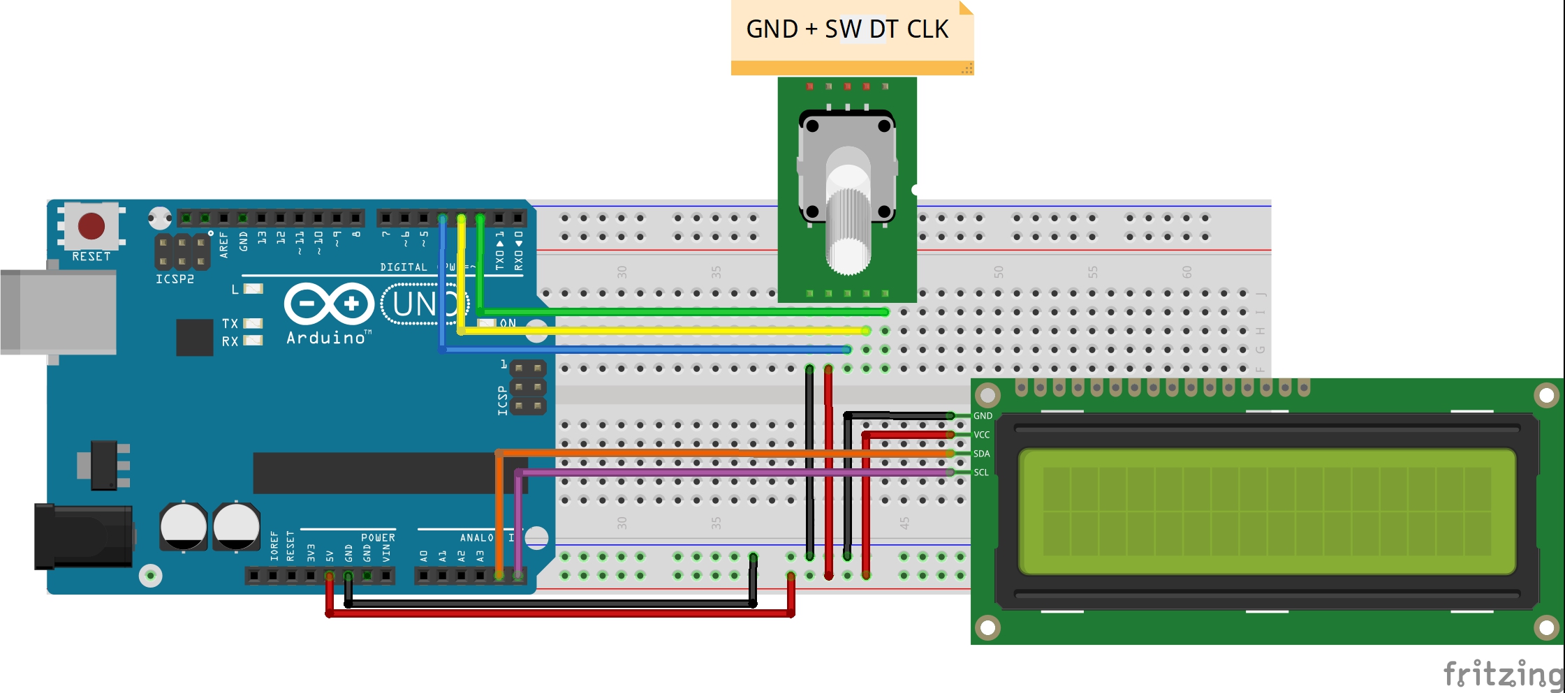
Count the encoder position and display it on the I2C 1602 LCD
Follow the last example, we will show the count of the encoder on the I2C 1602 LCD display.
Connection
Build the circuit as below:
| Rotary Encoder |
Arduino |
| CLK |
D2 |
| DT |
D3 |
| SW |
D4 |
| + |
+5V |
| GND |
GND |
| I2C 1602 LCD |
Arduino |
| VCC |
+5V |
| GND |
GND |
| SDA |
A4 |
| SCL |
A5 |
Code Program
After above operations are completed, connect the Arduino board to your computer using the USB cable. The green power LED (labelled PWR) should go on.Open the Arduino IDE and choose corresponding board type and port type for you project. Then load up the following sketch onto your Arduino.
#include <Wire.h> #include <LiquidCrystal_I2C.h> LiquidCrystal_I2C lcd(0x27,20,4); // set the LCD //address to 0x27 for a 16 chars and 2 line display const int clkPin= 2; //the clk attach to pin2 const int dtPin= 3; //the dt attach to pin3 const int swPin= 4 ;//the number of the button int encoderVal = 0; void setup() { lcd.init(); // initialize the lcd // Print a message to the LCD. lcd.backlight(); lcd.setCursor(0,0); lcd.print("The value is :"); //set clkPin,dePin,swPin as INPUT pinMode(clkPin, INPUT); pinMode(dtPin, INPUT); pinMode(swPin, INPUT); digitalWrite(swPin, HIGH); Serial.begin(9600); // initialize serial communications at 9600 bps } void loop() { int change = getEncoderTurn(); encoderVal = encoderVal + change; if(digitalRead(swPin) == LOW)//if button pull down { encoderVal = 0; lcd.clear(); lcd.setCursor(0,0); lcd.print("The value is :"); } Serial.println(encoderVal); //print the encoderVal on the serial monitor lcd.setCursor(5,1); lcd.print(encoderVal); } int getEncoderTurn(void) { static int oldA = HIGH; //set the oldA as HIGH static int oldB = HIGH; //set the oldB as HIGH int result = 0; int newA = digitalRead(dtPin);//read the value of clkPin to newA int newB = digitalRead(clkPin);//read the value of dtPin to newB if (newA != oldA || newB != oldB) //if the value of clkPin or the dtPin has changed { // something has changed if (oldA == HIGH && newA == LOW) { result = (oldB * 2 - 1); } } oldA = newA; oldB = newB; return result; }
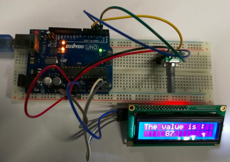
Running Result
A few seconds after the upload finishes, turn the rotary encoder clockwise, the angular displacement is increased; when turn it counterclockwise, the displacement is decreased.


The link for the LCD code returns a 404 error
try this link https://github.com/osoyoo/Osoyoo-development-kits/blob/master/Osoyoo%20lessons%20for%20Arduino/Rotary_Encoder/Rotary_Encoder.ino