Introduction
The digital temperature and humidity sensor DHT11 inside contains a chip that does analog to digital conversion and spits out a digital signal with the temperature and humidity, compatible with any MCUs, ideal for those who want some basic data logging stuffs. It’s very popular for electronics hobbyists because it is very cheap but still providing great performance.
In this lesson, we will first go into a little background about humidity, then we will explain how the DHT11 measures humidity. After that, we will show you how to connect the DHT11 to an Arduino and give you some example code so you can use the DHT11 in your own projects.
Preparations
HARDWARE
- Osoyoo UNO Board (Fully compatible with Arduino UNO rev.3) x 1
- DHT11 Sensor x 1
- I2C LCD1602 x 1
- 10k ohm Resistor x 1
- Breadboard x 1
- Jumpers
- USB Cable x 1
- PC x 1
About DHT11
The DHT11 is a basic, ultra low-cost digital temperature and humidity sensor. It uses a capacitive humidity sensor and a thermistor to measure the surrounding air, and spits out a digital signal on the data pin (no analog input pins needed). Its fairly simple to use, but requires careful timing to grab data.
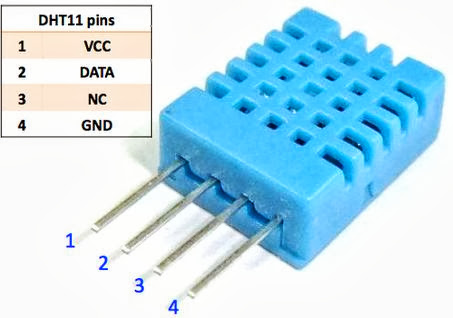
Only three pins are available for use: VCC, GND, and DATA. The communication process begins with the DATA line sending start signals to DHT11, and DHT11 receives the signals and returns an answer signal. Then the host receives the answer signal and begins to receive 40-bit humiture data (8-bit humidity integer + 8-bit humidity decimal + 8-bit temperature integer + 8-bit temperature decimal + 8-bit checksum).
WHAT IS RELATIVE HUMIDITY?
The DHT11 measures relative humidity. Relative humidity is the amount of water vapor in air vs. the saturation point of water vapor in air. At the saturation point, water vapor starts to condense and accumulate on surfaces forming dew.
The saturation point changes with air temperature. Cold air can hold less water vapor before it becomes saturated, and hot air can hold more water vapor before it becomes saturated.
The formula to calculate relative humidity is:
 \ x \ 100 \% \\ \\ RH: \ Relative \ Humidity \\ \rho_{w}: \ Density \ of \ water \ vapor\\ \rho_{s}: \ Density \ of \ water \ vapor \ at \ saturation")
Relative humidity is expressed as a percentage. At 100% RH, condensation occurs, and at 0% RH, the air is completely dry.
HOW THE DHT11 MEASURES HUMIDITY AND TEMPERATURE
The DHT11 detects water vapor by measuring the electrical resistance between two electrodes. The humidity sensing component is a moisture holding substrate with electrodes applied to the surface. When water vapor is absorbed by the substrate, ions are released by the substrate which increases the conductivity between the electrodes. The change in resistance between the two electrodes is proportional to the relative humidity. Higher relative humidity decreases the resistance between the electrodes, while lower relative humidity increases the resistance between the electrodes.
The DHT11 measures temperature with a surface mounted NTC temperature sensor (thermistor) built into the unit.
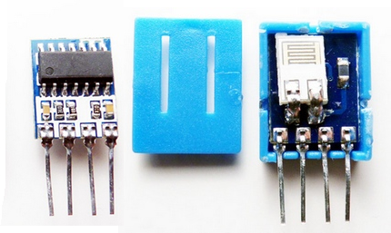
With the plastic housing removed, you can see the electrodes applied to the substrate, an IC mounted on the back of the unit converts the resistance measurement to relative humidity. It also stores the calibration coefficients, and controls the data signal transmission between the DHT11 and the Arduino:
DIFFRENCES BETWEEN DHT11 AND DHT22

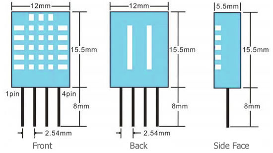
DIMENSION OF DHT11
DHT11 MODULE
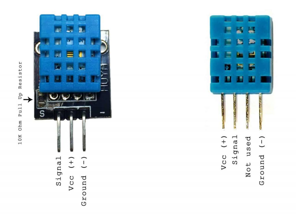
There are two different versions of the DHT11 you might come across. One type has four pins, and the other type has three pins and is mounted to a small PCB. The PCB mounted version is nice because it includes a surface mounted 10K Ohm pull up resistor for the signal line. Here are the pin outs for both versions:
Examples
DISPLAY HUMIDITY AND TEMPERATURE ON THE SERIAL MONITOR
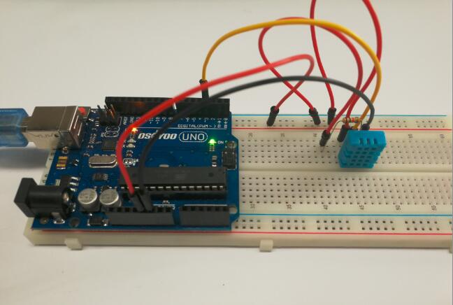
Connection
Build the circuit as below:
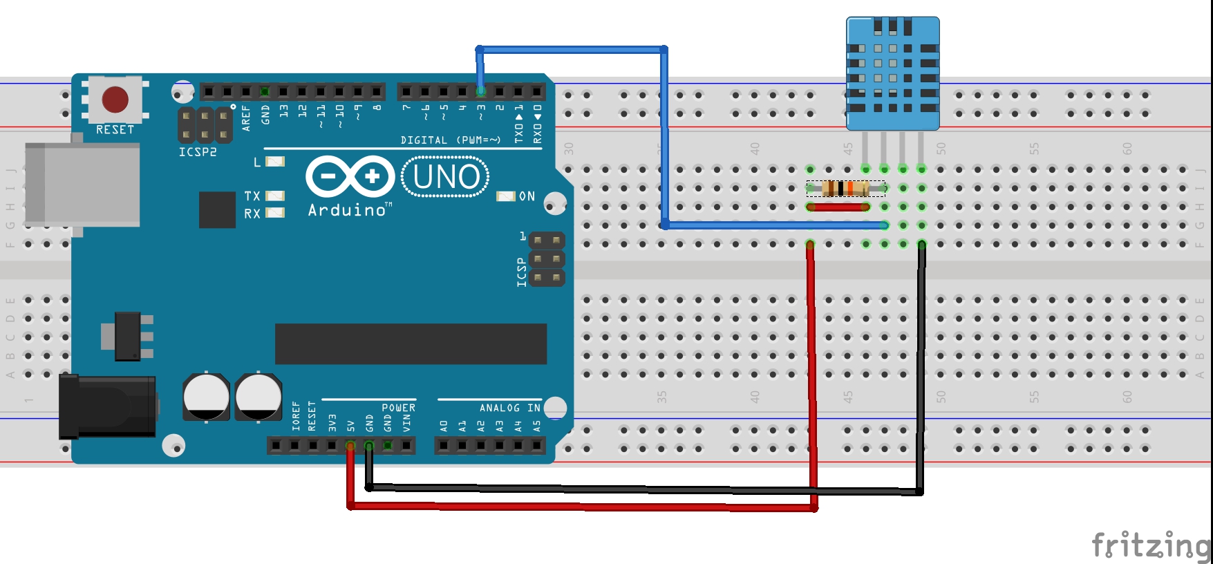
Simply ignore pin 3 of DHT11, its not used. You will want to place a 10K resistor between VCC and the data pin, to act as a medium-strength pull up on the data line. The Arduino has built in pullups you can turn on but they’re very weak, about 20-50K
This diagram shows how we will connect for the testing sketch. Connect data to pin 3, you can change it later to any pin.
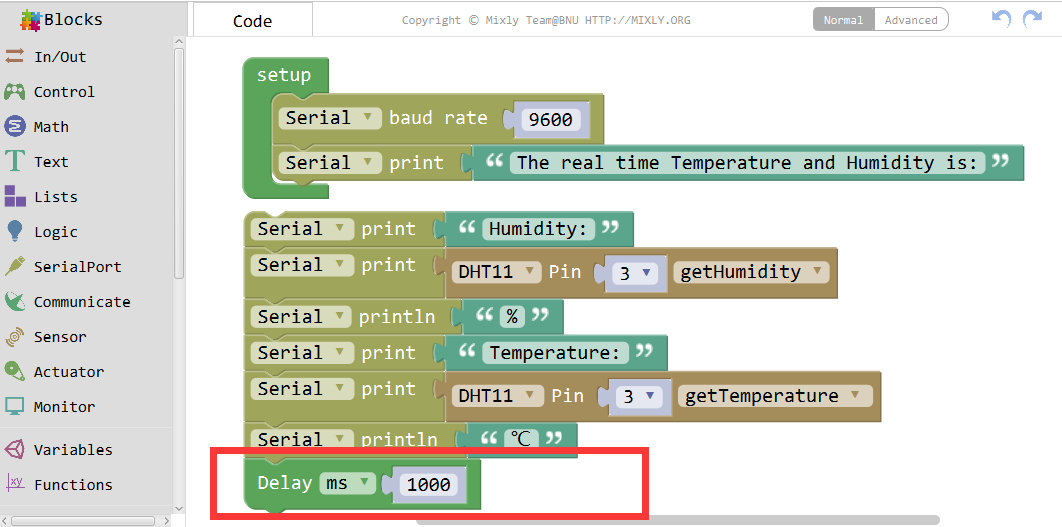
CODE PROGRAM
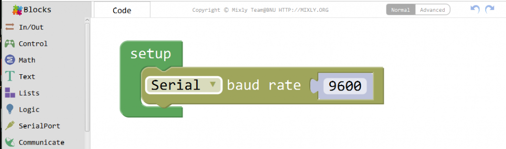
After above operations are completed, connect the Arduino board to your computer using the USB cable. The green power LED (labelled PWR) should go on.Open the Graphical Programming software Mixly and follow the next operations:
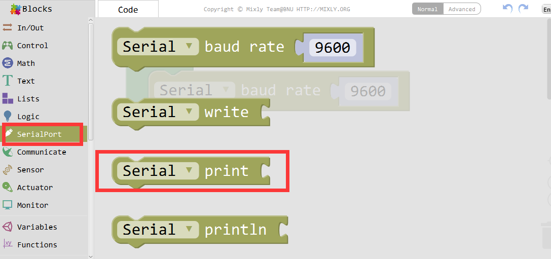
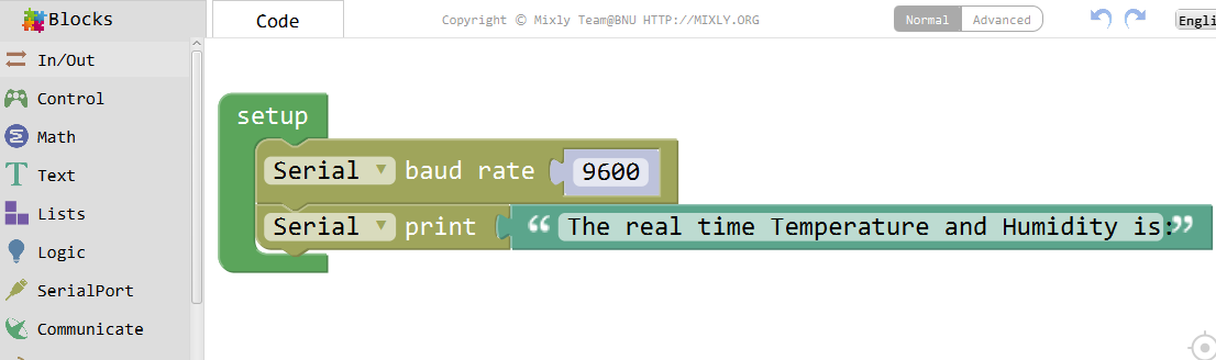
Set the serial baudrate as 9600.
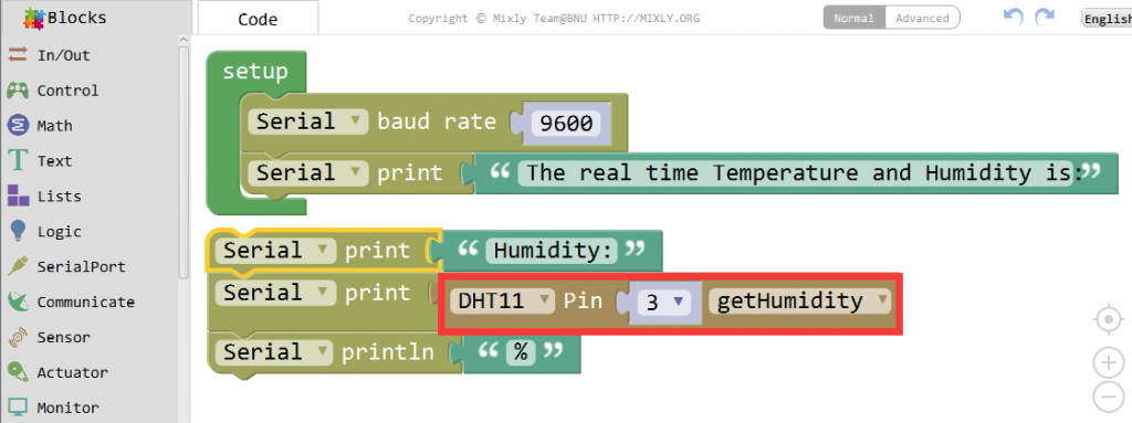
Choose the Serial print fuction and drag it to the blank area.

Add some text to the code as below.

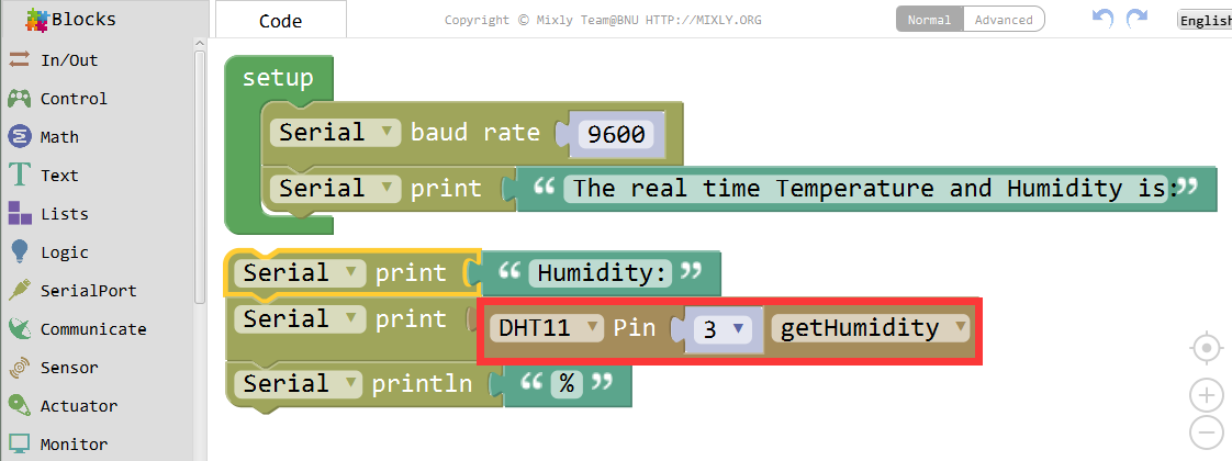
Find the Sensor block and select the DHT11 related funtion.

Follow the code, and you will get the humidity data from the DHT11 sensor.
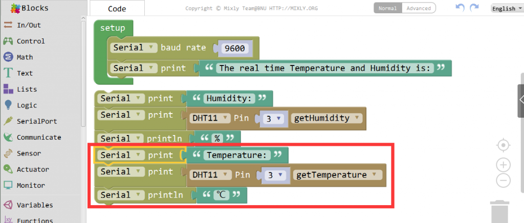
Now, add some similar code to get the real time temperature.
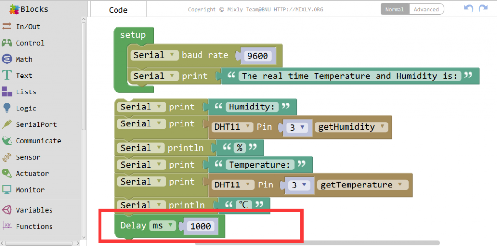
At last, we drag a Delay block and set the value to 1000ms.
Running Result
A few seconds after the upload finishes, open the Serial Monitor, you should now see the humidity and temperature readings displayed at one second intervals.

Note: Please make sure you have choosed the correct port and the correct baudrate for you project.