概述
上一讲中,我们学会了如何驱动MCP3008 ADC,在更早的时候也讲过通过对硬件PWM编程控制LED亮度的实验,在本课中,我们将讲解如何用MCP3008读取光敏电阻光照度,通过光照强度控制LED亮度。
所需器件
1 * Raspberry Pi
1 * Breadboard
1 * 10K电阻
1 * 光敏电阻
Jumper wires
1 * T-Extension Board
1 * 40-Pin Cable
工作原理
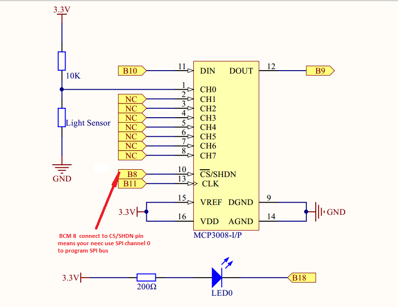
光敏电阻是一种阻值可变的特殊电阻,其阻值会随着光照增强而减弱。光敏电阻常常别应用到光控开关电路或光检测电路中,例如日光灯等。在本课中我们利用MCP3008ADC读取光敏电阻两端电压,当光照强度变化时候,这个电压值也会随着变化,用MCP3008把读取到的电压值转换成数字量,将这个数字量作为PWM的输入值,从而控制LED亮度。
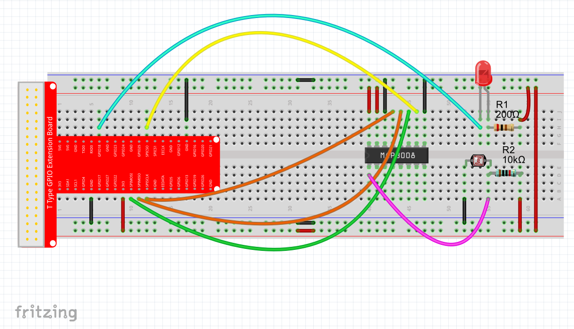
实物连接图
软件
对于C语言用户,请看下面
1) 在/home/pi下新建一个.c源文件(文件名随意)
cd ~
sudo nano lightsensor.c
2) 往新建的文件中写入一下代码
#include <unistd.h>
#include <stdint.h>
#include <string.h>
#include <errno.h>
#include <wiringPi.h>
#include <stdio.h>
#include <stdlib.h>
#include <wiringPiSPI.h>

//pin 1(BCM GPIO 18) is PWM  port
#define  LEDPIN   1

#define CHAN_CONFIG_SINGLE  8
#define SPICHANNEL          0
#define ANALOGCHANNEL       0
static int myFd ;

void spiSetup (int spiChannel)
{
    if ((myFd = wiringPiSPISetup (spiChannel, 10000)) < 0)
    {
        fprintf (stderr, "Can't open the SPI bus: %s\n", strerror (errno)) ;
        exit (EXIT_FAILURE) ;
    }
}

int myAnalogRead(int spiChannel,int channelConfig,int analogChannel)
{
    if(analogChannel<0 || analogChannel>7)
        return -1;
    unsigned char buffer[3] = {1}; // start bit
    buffer[1] = (channelConfig+analogChannel) << 4;
    wiringPiSPIDataRW(spiChannel, buffer, 3);
    return ( (buffer[1] & 3 ) << 8 ) + buffer[2]; // get last 10 bits
}

void print_info()
{
    printf("\n");
    printf("|************************************|\n");
    printf("|        MCP3008 read lightsensor    |\n");
    printf("|       -------------------------    |\n");
    printf("|       | ADC |           | Pi  |    |\n");
    printf("|       |-----|-----------|-----|    |\n");
    printf("|       | CS  | connect to| CE0 |    |\n");
    printf("|       | Din | connect to| MOSI|    |\n");
    printf("|       | Dout| connect to| MISO|    |\n");
    printf("|       | CLK | connect to| SCLK|    |\n");
    printf("|       | CH0 | connect to| 3.3V|    |\n");
    printf("|       | CH1 | connect to| GND |    |\n");
    printf("|************************************|\n");
    printf("|          LED connect to GPIO1      |\n");
    printf("|                              OSOYOO|\n");
    printf("|************************************|\n");
    printf("\n");

}

int main()
{
  int adc;
  if(wiringPiSetup()<0)
    {
      printf("setup wiringPi failed!\n");
            printf("please check your setup\n");
            exit(1);
    }
  spiSetup(SPICHANNEL);
  pinMode(LEDPIN,PWM_OUTPUT);
  print_info();

  for(;;)
  {
      adc = myAnalogRead(SPICHANNEL,CHAN_CONFIG_SINGLE,ANALOGCHANNEL);
            printf("ADC = %d\n",adc);
      pwmWrite(LEDPIN,1023-adc);
      delay(1000);
  }

}
代码绝大多数跟前的一样,这里只讲解前面没有出现过的。
  for(;;)
  {
      adc = myAnalogRead(SPICHANNEL,CHAN_CONFIG_SINGLE,ANALOGCHANNEL);
            printf("ADC = %d\n",adc);
      pwmWrite(LEDPIN,1023-adc);
      delay(1000);
  }
在主循环中读取光敏电阻电压值,将电压值通过MCP3008转换成对应的数字量,然后把这个对应的数字量作为pwmWrite(pin,value)函数的第二个参数,这样就实现了通过光照强度控制LED亮度的目的。
完整的源代码可以在终端运行一下命令获取
sudo wget http://osoyoo.com/driver/pi3_start_learning_kit_lesson_11/lightsensor.c
3) 编译
gcc -Wall -o lightsensor lightsensor.c -lwiringPi
4) 执行程序
sudo ./lightsensor
5) 最终结果
运行上面的程序,屏幕上首先会输出MCP3008以及LED与Raspberry Pi的连接关系,接着会输出光敏电阻的AD值。用手捂住光敏电阻会看到LED亮度变亮,用光对着光敏电阻照射,LED会变暗。
for python user
1) 在/home/pi下新建一个.py脚本文件,文件名随意(你爱咋咋地)
cd ~
sudo nano lightsensor.py
2) 编码
import time
import os
import RPi.GPIO as GPIO

# change these as desired - they're the pins connected from the
# SPI port on the ADC to the Cobbler
SPICLK = 11
SPIMISO = 9
SPIMOSI = 10
SPICS = 8
#set BCM_GPIO 18(GPIO1) as LED pin
LEDPIN = 18

analogChannel = 0

#setup function for some setup---custom function
def setup():
    global p
    GPIO.setwarnings(False)
    #set the gpio modes to BCM numbering
    GPIO.setmode(GPIO.BCM)
    # set up the SPI interface pins
    GPIO.setup(SPIMOSI, GPIO.OUT)
    GPIO.setup(SPIMISO, GPIO.IN)
    GPIO.setup(SPICLK, GPIO.OUT)
    GPIO.setup(SPICS, GPIO.OUT)
    #set all LedPin's mode to output,and initial level to HIGH(3.3V)
    GPIO.setup(LEDPIN,GPIO.OUT,initial=GPIO.LOW)
    #set LEDPIN as PWM output,and frequency=100Hz
    p = GPIO.PWM(LEDPIN,100)
    #set p begin with ualue 0
    p.start(0)
    pass


#print message at the begining ---custom function
def print_message():
    print ('|**********************************|')
    print ('|   MCP3008 read lightsensor   |')
    print ('|   -----------------------------  |')
    print ('|    | ADC |           | Pi  |     |')
    print ('|    |-----|-----------|-----|     |')
    print ('|    | CS  | connect to| CE0 |     |')
    print ('|    | Din | connect to| MOSI|     |')
    print ('|    | Dout| connect to| MISO|     |')
    print ('|    | CLK | connect to| SCLK|     |')
    print ('|    | CH0 | connect to| 3.3V|     |')
    print ('|    | CH1 | connect to| GND |     |')
    print ('| ********************************** |')
    print (' LED connect to GPIO1')
    print ('|                            OSOYOO|')
    print ('|**********************************|\n')
    print ('Program is running...')
    print ('Please press Ctrl+C to end the program...')

# read SPI data from MCP3008 chip, 8 possible adc's (0 thru 7)
def readadc(adcnum, clockpin, mosipin, misopin, cspin):
        if ((adcnum > 7) or (adcnum < 0)):
                return -1
        GPIO.output(cspin, True)

        GPIO.output(clockpin, False)  # start clock low
        GPIO.output(cspin, False)     # bring CS low

        commandout = adcnum
        commandout |= 0x18  # start bit + single-ended bit
        commandout <<= 3    # we only need to send 5 bits here
        for i in range(5):
                if (commandout & 0x80):
                        GPIO.output(mosipin, True)
                else:
                        GPIO.output(mosipin, False)
                commandout <<= 1
                GPIO.output(clockpin, True)
                GPIO.output(clockpin, False)

        adcout = 0
        # read in one empty bit, one null bit and 10 ADC bits
        for i in range(12):
                GPIO.output(clockpin, True)
                GPIO.output(clockpin, False)
                adcout <<= 1
                if (GPIO.input(misopin)):
                        adcout |= 0x1

        GPIO.output(cspin, True)

        adcout >>= 1       # first bit is 'null' so drop it
        return adcout

#main function
def main():
    while True:
        #print info
        print_message()
        adc = readadc(analogChannel, SPICLK, SPIMOSI, SPIMISO, SPICS)
        print ('LightSensor ADC = %d'%(adc))
        adc=(1023-adc)*100/1023
        p.ChangeDutyCycle(int(adc))
        time.sleep(1)

#define a destroy function for clean up everything after the script finished
def destroy():
    #stop p
    p.stop()
    #turn off led
    GPIO.output(LEDPIN,GPIO.LOW)
    #release resource
    GPIO.cleanup()

#
# if run this script directly ,do:
if __name__ == '__main__':
    setup()
    try:
            main()
    #when 'Ctrl+C' is pressed,child program destroy() will be executed.
    except KeyboardInterrupt:
        destroy()
代码绝大多数跟前的一样,这里只讲解前面没有出现过的。
        adc=(1023-adc)*100/1023
        p.ChangeDutyCycle(int(adc))
因为MCP3008是10位分辨率的ADC,所以输出值范围是0-1023,但是ChangeDutyCycle(int value)函数的参数value的范围是0-100的数,所以需要将0-1023转换成0-100,这里通过一个简单的算法实现了这个功能。
完整的脚本代码,可以通过下面的命令获取
sudo wget http://osoyoo.com/driver/pi3_start_learning_kit_lesson_11/lightsensor.py
3) 执行脚本
sudo python ./lightsensor.py
4) 最终结果
运行上面的脚本,屏幕上首先会输出MCP3008以及LED与Raspberry Pi的连接关系,接着会输出光敏电阻的AD值。用手捂住光敏电阻会看到LED亮度变亮,用光对着光敏电阻照射,LED会变暗。


