Note: ALL OSOYOO Products for Arduino are Third Party Board which is fully compatitable with Arduino
Authorized Online Retailers:
Content
- Introduction
- Preparations
- About the Servo
- Examples
Introduction
Servo motors are great devices that can turn to a specified position. Usually, they have a servo arm that can turn 180 degrees. Using the Arduin, we can tell a servo to go to a specified position and it will go there. As simple as that!
Servo motors were first used in the Remote Control (RC) world, usually to control the steering of RC cars or the flaps on a RC plane. With time, they found their uses in robotics, automation, and of course, the Arduin world.
In this lesson, you will learn how to control a servo motor using an Arduin.
Firstly, you will get the servo to sweep back and forth automatically and then you will add a pot to control the position of the servo.
Preparations
Hardware
- Osoyoo Basic Board (Fully compatible with Arduino UNO rev.3) x 1
- Servo Motor SG90 x 1
- 10k ohm Potentiometer x 1
- Breadboard x 1
- Jumpers
- USB Cable x 1
- PC x 1
Software
- Arduino IDE (version 1.6.4+)
- Servo.h
About Servo
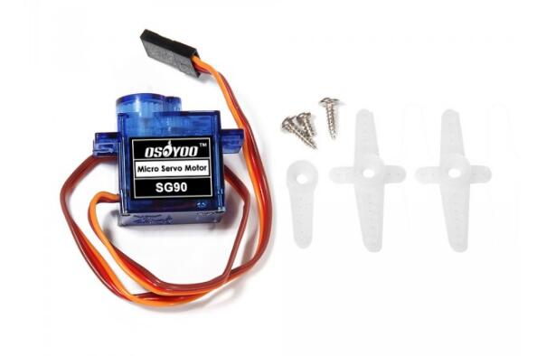
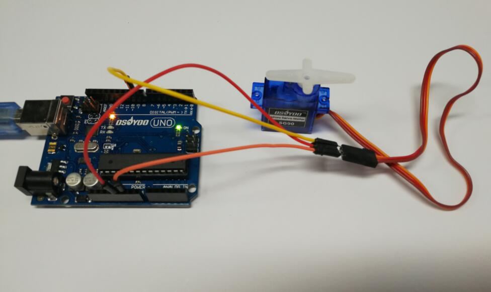
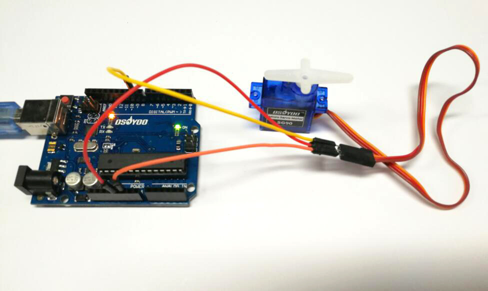
Servo consists of shell, circuit board, non-core motor, gear and location detection.The servo motor has three leads. The color of the leads varies between servo motors, but the red lead is always 5V and GND will either be black or brown. The other lead is the control lead and this is usually orange or yellow. This control lead is connected to digital pin 9.
How it work ?
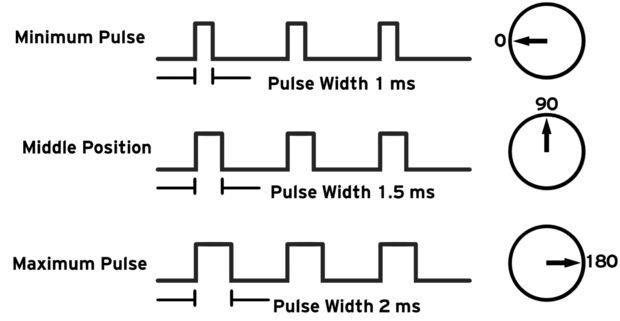
Servos are clever devices. Using just one input pin, they receive the position from the Arduin and they go there. Internally, they have a motor driver and a feedback circuit that makes sure that the servo arm reaches the desired position. But what kind of signal do they receive on the input pin?
It is a square wave similar to PWM. Each cycle in the signal lasts for 20 milliseconds and for most of the time, the value is LOW. At the beginning of each cycle, the signal is HIGH for a time between 1 and 2 milliseconds. At 1 millisecond it represents 0 degrees and at 2 milliseconds it represents 180 degrees. In between, it represents the value from 0–180. This is a very good and reliable method. The graphic makes it a little easier to understand.
What you should note ?
our servo may behave erratically, and you may find that this only happens when the Arduin is plugged into certain USB ports. This is because the servo draws quite a lot of power, especially as the motor is starting up, and this sudden high demand can be enough to drop the voltage on the board, so that it resets itself.
If this happens, then you can usually cure it by adding a high value capacitor (470uF or greater) between GND and 5V on the breadboard.
Learn more about the library — Servo.h
This library allows an board to control RC (hobby) servo motors. Servos have integrated gears and a shaft that can be precisely controlled. Standard servos allow the shaft to be positioned at various angles, usually between 0 and 180 degrees. Continuous rotation servos allow the rotation of the shaft to be set to various speeds.
The Servo library supports up to 12 motors on most boards and 48 on the Arduin Mega. On boards other than the Mega, use of the library disables analogWrite() (PWM) functionality on pins 9 and 10, whether or not there is a Servo on those pins. On the Mega, up to 12 servos can be used without interfering with PWM functionality; use of 12 to 23 motors will disable PWM on pins 11 and 12.
Circuit

Servo motors have three wires: power, ground, and signal. The power wire is typically red, and should be connected to the 5V pin on the board. The ground wire is typically black or brown and should be connected to a ground pin on the board. The signal pin is typically yellow, orange or white and should be connected to a digital pin on the board. Note that servos draw considerable power, so if you need to drive more than one or two, you’ll probably need to power them from a separate supply (i.e. not the +5V pin on your Arduin). Be sure to connect the grounds of the Arduin and external power supply together.
Examples
Servo Sweep
At this part, we will show how to use the Osoyoo Uno to sweeps the shaft of a RC servo motor back and forth across 180 degrees.
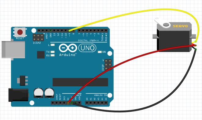
Connection
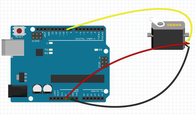
As we can see from above, servo motors have three wires: power, ground, and signal. The power wire is typically red, and should be connected to the 5V pin on the Arduin or Genuino board. The ground wire is typically black or brown and should be connected to a ground pin on the board. The signal pin is typically yellow, orange or white and should be connected to pin 9 on the board.
Build the circuit as below:
Upload Sketch
After above operations are completed, connect the board to your computer using the USB cable. The green power LED (labelled PWR) should go on. Load up the following sketch onto your board. You should find that the servo immediately begins to turn first in one direction and then back in the other.
#include <Servo.h>
Servo myservo; // create servo object to control a servo
// twelve servo objects can be created on most boards
int pos = 0; // variable to store the servo position
void setup() {
myservo.attach(9); // attaches the servo on pin 9 to the servo object
} void loop() {
for (pos = 0; pos <= 180; pos += 1) {
// goes from 0 degrees to 180 degrees //
in steps of 1 degree
myservo.write(pos); // tell servo to go to position in variable 'pos'
delay(15); // waits 15ms for the servo to reach the position
}
for (pos = 180; pos >= 0; pos -= 1) {
// goes from 180 degrees to 0 degrees
myservo.write(pos); // tell servo to go to position in variable 'pos'
delay(15); // waits 15ms for the servo to reach the position
}
}
Running Result
A few seconds after the upload finishes, you should now see:
Control servo motor rotate degrees
Servo is a type of geared motor that can only rotate 180 degrees. It is controlled by sending electrical pulses from your Osoyoo Uno board. These pulses tell the servo what position it should move to. At this part, we control the servo motor rotate 90 degrees (rotate once every 15 degrees),
And then rotate in the opposite direction.
Upload Sketch
The circuit digram is same as above example, so just load up the following sketch onto your Arduin:
#include <Servo.h>
Servo myservo;
//create servo object to control a servo
void setup() {
myservo.attach(9);//attachs the servo on pin 9 to servo object
myservo.write(0);//back to 0 degrees
delay(1000);//wait for a second
}
void loop() {
myservo.write(15);//goes to 15 degrees
delay(1000);//wait for a second
myservo.write(30);//goes to 30 degrees
delay(1000);//wait for a second.33
myservo.write(45);//goes to 45 degrees
delay(1000);//wait for a second.33
myservo.write(60);//goes to 60 degrees
delay(1000);//wait for a second.33
myservo.write(75);//goes to 75 degrees
delay(1000);//wait for a second.33
myservo.write(90);//goes to 90 degrees
delay(1000);//wait for a second
myservo.write(75);//back to 75 degrees
delay(1000);//wait for a second.
myservo.write(60);//back to 60 degrees d
elay(1000);//wait for a second.
myservo.write(45);//back to 45 degrees
delay(1000);//wait for a second.
myservo.write(30);//back to 30 degrees
delay(1000);//wait for a second.
myservo.write(15);//back to 15 degrees
delay(1000);//wait for a second
myservo.write(0);//back to 0 degrees
delay(1000);//wait for a second
}
Running Result
A few seconds after the upload finishes, you should now see the servo motor rotate 90 degrees (rotate once every 15 degrees). And then rotate in the opposite direction.
Servo Knob
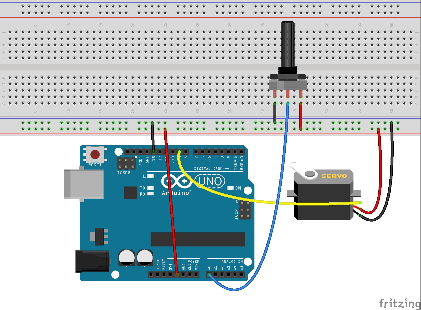
At this part, we will show how to control the position of a RC (hobby) servo motor with your Arduin and a potentiometer. You just need to add the pot and a lead from its slider to A0 on the Arduin.
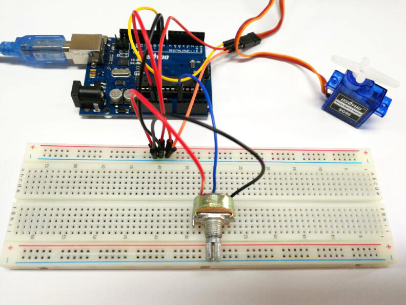
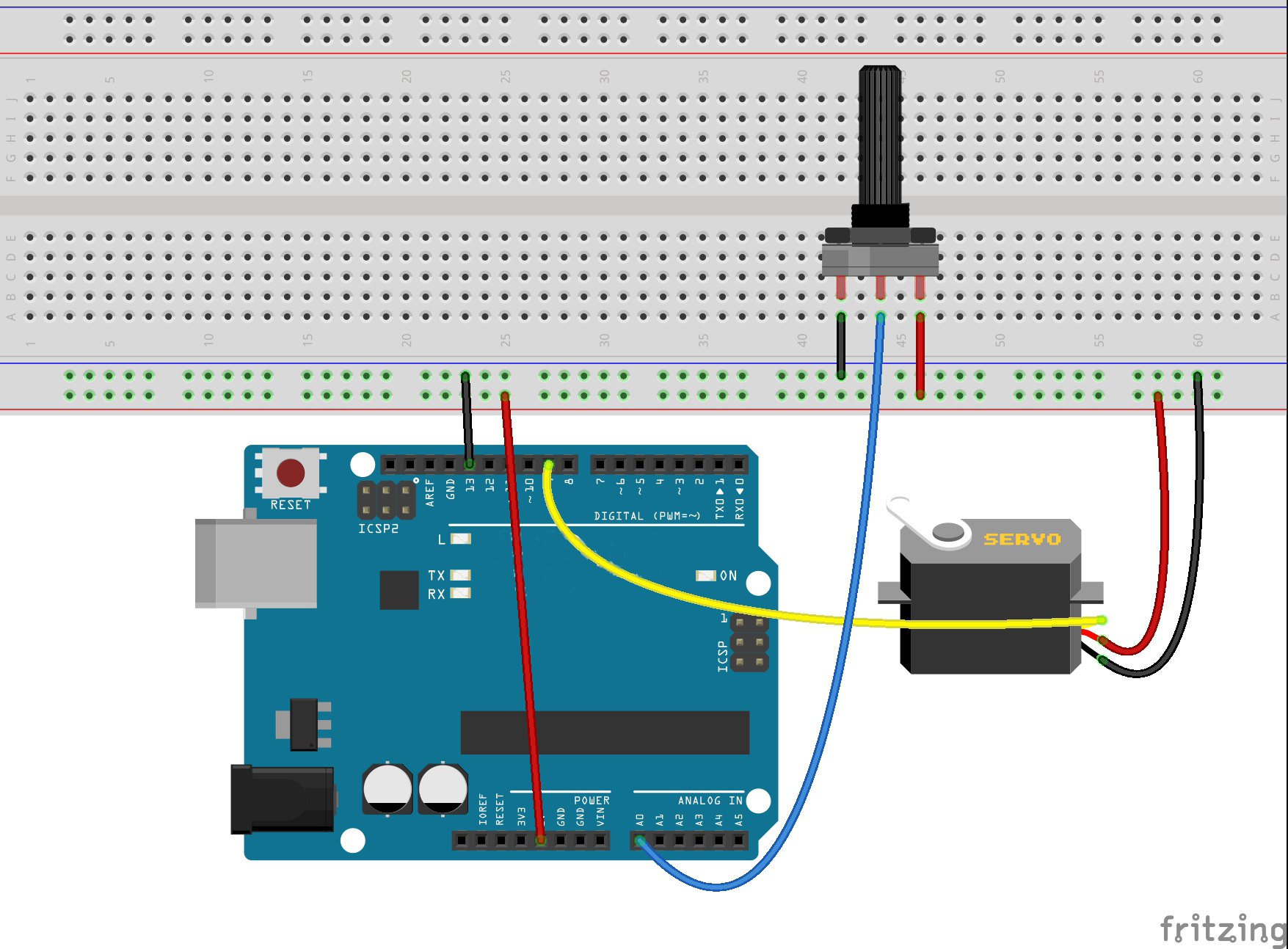
Connection
The potentiometer should be wired so that its two outer pins are connected to power (+5V) and ground, and its middle pin is connected to analog input 0 on the board. So, build the circuit as below:
Code for ‘Knob’
The code to make the servo follow the knob’s position is simpler than to make it sweep.
#include <Servo.h>
Servo myservo; // create servo object to control a servo
int potpin = 0; // analog pin used to connect the potentiometer
int val; // variable to read the value from the analog pin
void setup() {
myservo.attach(9); // attaches the servo on pin 9 to the servo object
}
void loop() {
val = analogRead(potpin); // reads the value of the potentiometer (value between 0 and 1023)
val = map(val, 0, 1023, 0, 180); // scale it to use it with the servo (value between 0 and 180)
myservo.write(val); // sets the servo position according to the scaled value
delay(15); // waits for the servo to get there
}
There is now a second variable called ‘potPin’.
To set the position of the servo, we take an analog reading from A0. This gives us a value of between 0 and 1023. Since the servo can only rotate through 180 degrees, we need to scale this down (value between 0 and 180).
Running Result
A few seconds after the upload finishes, you should now control the position of a servo with a potentiometer, such as below operation: