Note: ALL OSOYOO Products for Arduino are Third Party Board which is fully compatitable with Arduino
Authorized Online Retailers:
Content
- Introduction
- Preparations
- About the 74HC595
- Examples
Introduction
At sometime or another you may run out of pins on your board and need to extend it with shift registers. This example is based on the 74HC595. The datasheet refers to the 74HC595 as an “8-bit serial-in, serial or parallel-out shift register with output latches; 3-state.” In other words, you can use it to control 8 outputs at a time while only taking up a few pins on your microcontroller. You can link multiple registers together to extend your output even more.
In this lesson, we will show how to use the 74HC595 8-bit shift register with Osoyoo Basic boards.
Preparations
Hardware
- Osoyoo Basic Board (Fully compatible with Arduino UNO rev.3) x 1
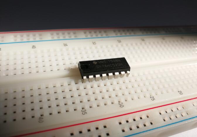
- 74HC595 x 1
- LED x 8
- One-digit 7 Segment LED Display x 1
- 200 ohm Resistor x 8
- Breadboard x 1
- Jumpers
- USB Cable x 1
- PC x 1
Software
- Arduino IDE (version 1.6.4+)
About 74HC595
Before I go through the circuit, let’s have a quick look at what the chip is doing, so that we can understand what the code has to do.
The first thing that should be cleared up is what “bits” are, for those of you who aren’t familiar with binary. When we refer to a “bit”, we are referring to one of the numbers that make up the binary value. Unlike normal numbers though, we typically consider the first bit to be the right most one. So, if we take the binary value 10100010, the first bit is actually 0, and the eighth bit is 1. It should also be noted, in case it wasn’t implied, each bit can only be 0 or 1.
The chip contains eight pins that we can use for output, each of which is associated with a bit in the register. In the case of the 74HC595 IC, we refer to these as QA through to QH. In order to write to these outputs via the Arduin, we have to send a binary value to the shift register, and from that number the shift register can figure out which outputs to use. For example, if we sent the binary value 10100010, the pins highlighted in green in the image below would be active and the ones highlighted in red would be inactive.
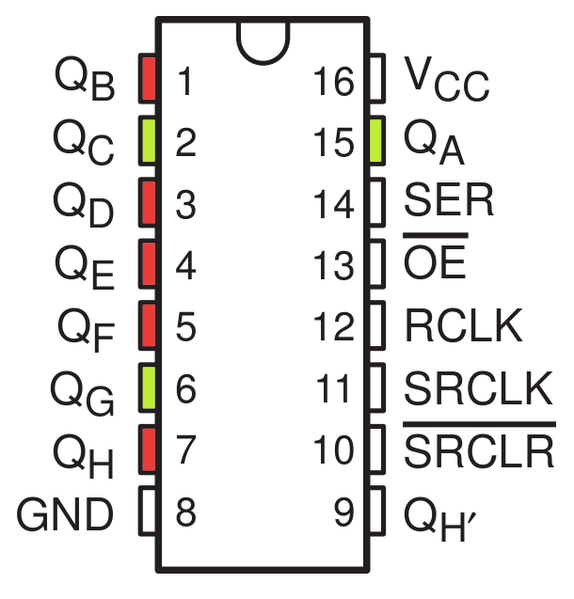
This means that the right most bit that we specify maps to QH, and the left most bit maps to QA. An output is considered active when the bit mapped to it is set to 1. It is important to remember this, as otherwise you will have a very hard time knowing which pins you are using!
The chip also has an OE (output enable) pin, this is used to enable or disable the outputs all at once. You could attach this to a PWM capable Arduin pin and use ‘analogWrite’ to control the brightness of the LEDs. This pin is active low, so we tie it to GND.
Now that we have a basic understanding of how we use bit shifting to specify which pins to use, we can begin hooking it up to our Arduin!
Examples
LEDs and a Shift Register
Arduin includes a special function called ‘shiftOut’ that is designed specifically for sending data to shift registers. Here is the full sketch, the discussion of how it works follows on from it.
Connection
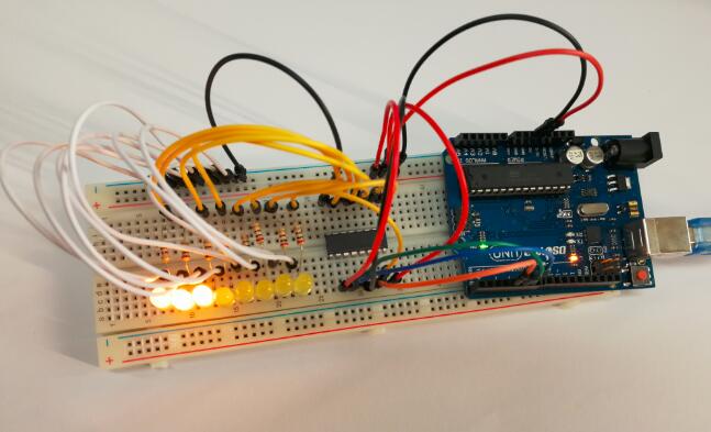
Build the circuit as below:
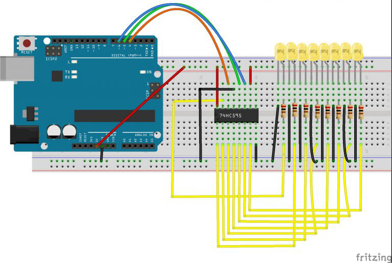
It is probably easiest to put the 74HC595 chip in first, as pretty much everything else connects to it. Put it so that the little U-shaped notch is towards the top of the breadboard. Pin 1 of the chip is to the left of this notch.
- Digital 4 from the arduin goes to pin #14 of the shift register
- Digital 5 from the arduin goes to pin #12 of the shift register
- Digital 6 from the arduin goes to pin #11 of the shift register
All but one of the outputs from the ‘595 are on the left hand side of the chip, hence, for ease of connection, that is where the LEDs are too.
After the chip, put the resistors in place. You need to be careful that none of the leads of the resistors are touching each other. You should check this again, before you connect the power to your board. If you find it difficult to arrange the resistors without their leads touching, then it helps to shorten the leads so that they are lying closer to the surface of the breadboard.Next, place the LEDs on the breadboard.
The longer positive LED leads must all be towards the chip, whichever side of the breadboard they are on.
It now just remains to attach the jumper leads as shown above. Do not forget the one that goes from pin 8 of the IC to the GND column of the breadboard.
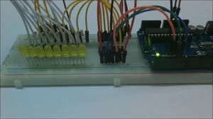
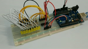
Load up the sketch listed a bit later and try it out. Each LED should light in turn until all the LEDs are on, and then they all go off and the cycle repeats.
Upload Sketch
After above operations are completed, connect the board to your computer using the USB cable. The green power LED (labelled PWR) should go on. Load up the following sketch onto your board.
int latchPin = 5;
int clockPin = 6;
int dataPin = 4;

byte leds = 0;

void setup()
{
  pinMode(latchPin, OUTPUT);
  pinMode(dataPin, OUTPUT);
  pinMode(clockPin, OUTPUT);
}

void loop()
{
  leds = 0;
  updateShiftRegister();
  delay(500);
  for (int i = 0; i < 8; i++)
  {
    bitSet(leds, i);
    updateShiftRegister();
    delay(500);
  }
}

void updateShiftRegister()
{
   digitalWrite(latchPin, LOW);
   shiftOut(dataPin, clockPin, LSBFIRST, leds);
   digitalWrite(latchPin, HIGH);
}
The first thing we do is define the three pins we are going to use. These are the Arduin digital outputs that will be connected to the latch, clock and data pins of the 74HC595.
int latchPin = 5;
int clockPin = 6;
int dataPin = 4;
Next, a variable called ‘leds’ is defined. This will be used to hold the pattern of which LEDs are currently turned on or off. Data of type ‘byte’ represents numbers using eight bits. Each bit can be either on or off, so this is perfect for keeping track of which of our eight LEDs are on or off.
byte leds = 0;
The ‘setup’ function just sets the three pins we are using to be digital outputs.
void setup()
{
  pinMode(latchPin, OUTPUT);
  pinMode(dataPin, OUTPUT);
  pinMode(clockPin, OUTPUT);
}
The ‘loop’ function initially turns all the LEDs off, by giving the variable ‘leds’ the value 0. It then calls ‘updateShiftRegister’ that will send the ‘leds’ pattern to the shift register so that all the LEDs turn off. We will deal with how ‘updateShiftRegister’ works later.
The loop function pauses for half a second and then begins to count from 0 to 7 using the ‘for’ loop and the variable ‘i’. Each time, it uses the Arduin function ‘bitSet’ to set the bit that controls that LED in the variable ‘leds’. It then also calls ‘updateShiftRegister’ so that the leds update to reflect what is in the variable ‘leds’.
There is then a half second delay before ‘i’ is incremented and the next LED is lit.
void loop()
{
  leds = 0;
  updateShiftRegister();
  delay(500);
  for (int i = 0; i < 8; i++)
  {
    bitSet(leds, i);
    updateShiftRegister();
    delay(500);
  }
}
The function ‘updateShiftRegister’, first of all sets the latchPin to low, then calls the Arduin function ‘shiftOut’ before putting the ‘latchPin’ high again. This takes four parameters, the first two are the pins to use for Data and Clock respectively.
The third parameter specifies which end of the data you want to start at. We are going to start with the right most bit, which is referred to as the ‘Least Significant Bit’ (LSB).
The last parameter is the actual data to be shifted into the shift register, which in this case is ‘leds’.
void updateShiftRegister()
{
   digitalWrite(latchPin, LOW);
   shiftOut(dataPin, clockPin, LSBFIRST, leds);
   digitalWrite(latchPin, HIGH);
}
If you wanted to turn one of the LEDs off rather than on, you would call a similar Arduin function (bitClear) on the ‘leds’ variable. This will set that bit of ‘leds’ to be 0 and you would then just need to follow it with a call to ‘updateShiftRegister’ to update the actual LEDs.
Running Result
A few seconds after the upload finishes, each LED should light in turn until all the LEDs are on, and then they all go off and the cycle repeats.
Control Led Brightness
One pin of the 74HC595 that I have not mentioned is a pin called ‘Output Enable’. This is pin 13 and on the breadboard, it is permanently connected to Ground. This pin acts as a switch, that can enable or disable the outputs – the only thing to watch for is it is ‘active low’ (connect to ground to enable). So, if it is connected to 5V, all the outputs go off. Whereas if it is connected to Ground, those outputs that are supposed to be on are on and those that should be off are off.
Connection
Build the circuit as below:
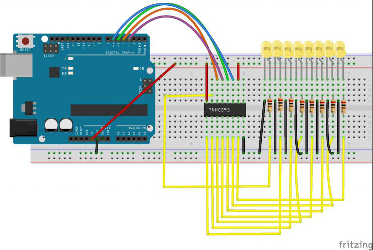
We can use this pin along with the ‘analogWrite’ function, to control the brightness of the LEDs using PWM.
To do this, all you need to do, is to change the connection to pin 13 of the 74HC595 so that instead of connecting it to Ground, you connect it to pin 3 of the board.
Upload Sketch
Load the sketch below, will once all the LEDs have been lit gradually fade them back to off.
int latchPin = 5;
int clockPin = 6;
int dataPin = 4;
int outputEnablePin = 3;

byte leds = 0;

void setup()
{
  pinMode(latchPin, OUTPUT);
  pinMode(dataPin, OUTPUT);
  pinMode(clockPin, OUTPUT);
  pinMode(outputEnablePin, OUTPUT);
}

void loop()
{
  setBrightness(255);
  leds = 0;
  updateShiftRegister();
  delay(500);
  for (int i = 0; i < 8; i++)
  {
    bitSet(leds, i);
    updateShiftRegister();
    delay(500);
  }
  for (byte b = 255; b > 0; b--)
  {
    setBrightness(b);
    delay(50);
  }
}

void updateShiftRegister()
{
   digitalWrite(latchPin, LOW);
   shiftOut(dataPin, clockPin, LSBFIRST, leds);
   digitalWrite(latchPin, HIGH);
}

void setBrightness(byte brightness) // 0 to 255
{
  analogWrite(outputEnablePin, 255-brightness);
}
Running Result
If you’ve completed all these steps correctly you should have something similar to that in the gif below.