Purchase link:
https://osoyoo.store/products/osoyoo-model-x-motor-driver-module-for-arduino-v2-0-robot-carmodel-2018000800?variant=31648878755951
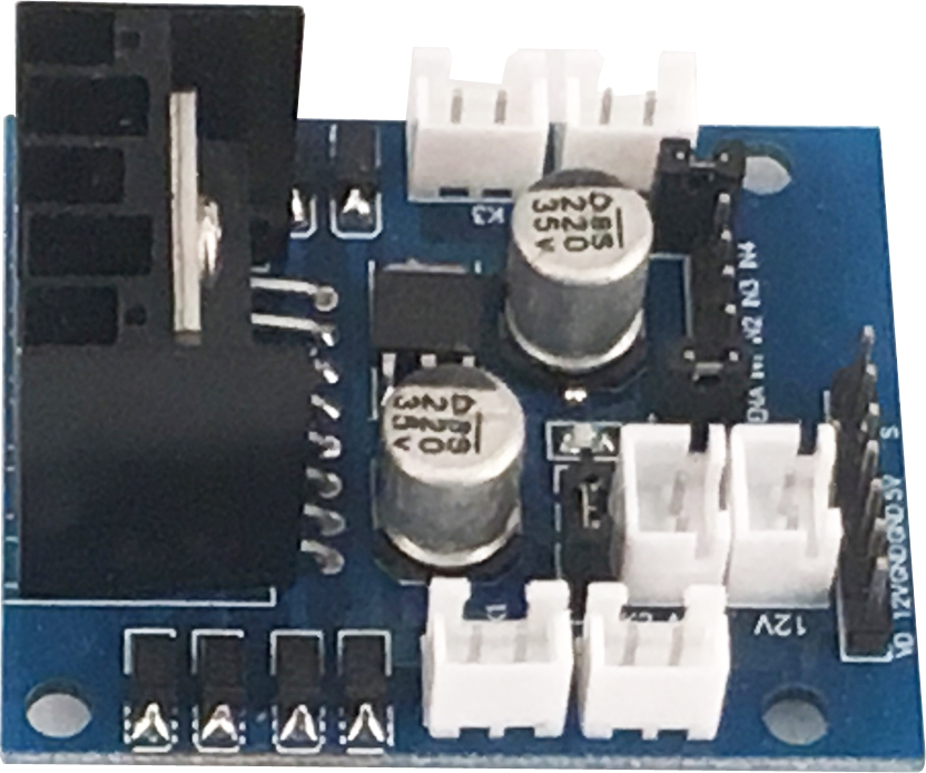
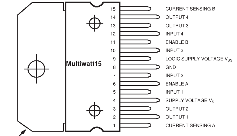
The OSOYOO Model-X Motor Driver Module is an integrated monolithic circuit in a 15- lead Multiwatt and PowerSO20 packages. It is a high voltage , high current dual full-bridge driver de-signed to accept standard TTL logic level sand drive inductive loads such as relays, solenoids, DC and stepping motors. Two enable inputs are provided to enable or disable the device independently of the in-put signals .The emitters of the lower transistors of each bridge are connected together rand the corresponding external terminal can be used for the connection of an external sensing resistor. An additional Supply input is provided so that the logic works at a lower voltage
OSOYOO Model-X Motor Driver Module is an improved L298N module which has newly designed wiring sockets and can greatly simplify the assembly procedure and wire connection stability.
Features
1) High operating voltage, which can be up to 40 volts;
2) Large output current, the instantaneous peak current can be up to 3A;
3) With 25W rated power;
4) Two built in H-bridge, high voltage, large current, full bridge driver, which can be used to drive DC motors, stepper motors, relay coils and other inductive loads.
5) Using standard logic level signal to control.
6) Able to drive a two-phase stepper motor or four-phase stepper motor, and two-phase DC motors.
7) Adopt a high-capacity filter capacitor and a freewheeling diode that protects devices in the circuit from being damaged by the reverse current of an inductive load, enhancing reliability
8) The module can utilize the built-in stabilivolt tube 78M05 to obtain 5v from the power supply. But to protect the chip of the 78M05 from damage, when the drive voltage is greater than 12v, an external 5v logic supply should be used.
9) Drive voltage: 5-35V; logic voltage: 5V
10) PCB size: 4.2 x 4.2 cm
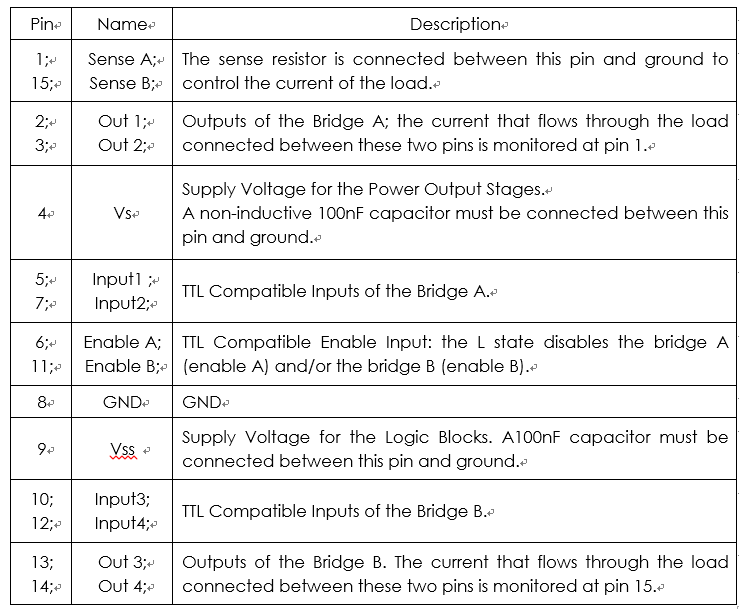
Pin Function for OSOYOO Model-X Motor Driver Module
Principle
The driver module can drive two motors. The enabled terminals ENA and ENB are effective at high level. The control mode and state of motor A are as shown in table (2):
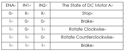
(2) Table for control mode and state of motor A
If you want to regulate the speed of motor A by PWM, you need to set IN1 and IN2, confirm the rotational direction of the motor, and then output PWM pulses for enabled terminals. Please note the motor is in the free stop state when the signal of enabled terminal is 0. When the enabled signal is 1, if IN1 and IN2 are 00 or 11, the motor is in brake state, and the motor stops rotating. If IN1 is 0 and IN2 is 1, the motor A rotates clockwise; if IN1 is 1 and IN2 is 0, the motor A rotates counterclockwise. This is the control method for motor A. The control method for motor B is the same as that for motor A.
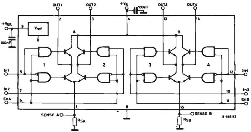
Block Diagram of OSOYOO Model-X Motor Driver Module
Application
The module can be applied to: – Drive DC motors. Since the module uses a dual H-bridge drive, it can drive two motors at the same time.
– Drive stepping motors. It can also drive two stepping motors synchronously.
Control Principle:
in following tables, 1=HIGH voltage(>3.3V), 0= LOW voltage (0V)
| ENA PWM signal |
Control rotation speed of motor in K1 and K2 |
| ENAB PWM signal |
Control rotation speed of motor in K3 and K4 |
| IN1/IN2 |
Control rotation direction of motor in K1 and K2 |
| IN3/IN4 |
Control rotation speed of motor in K3 and K2 |
| IN1=1 IN2=0 |
K1 and K2 rotate forward |
| IN1=0 IN2=1 |
K1 and K2 rotate backward |
| IN3=1 IN4=0 |
K3 and K4 rotate forward |
| IN3=0 IN4=1 |
K3 and K4 rotate backward |


Is it possible to have a full diagram of the board ?
What about the pins labelled: V0, 12V, GND, … on the pins row at the edge of the board. Are they input, output ?
Thanks
These pins are for our voltage meter.
Hello elaine,
can you please provide the schematics to the model-x driver board. All information on this site is just about the L298N module, but not the whole board?
I have the mecanum-wheel robot car kit, but I don’t just want to plug things together along your lessons, I want to understand the whole thing.
Thanks.
Please visit the picture: https://osoyoo.com/picture/V2.1_Arduino_Robot_Car/other/modelX.jpg
Thanks, thats not the schematics, but it helps. How much power can one soak on the +5V line? In case I would drive a different Servo?
It is equipped with a precision 500 mA voltage stabilizer, you have to consider the type and quantity of the motor you use
What is the VD 12V GND for? Can it be used for a 12V Mini water pump?
This is for our voltage meter. As we don’t have the 12V Mini water pump, I can’t make sure whether this motor driver can fit this pump. but it can drive 12V motors.
This is the pump link :
https://www.amazon.com/gp/product/B07XBYSHSM/ref=ppx_yo_dt_b_asin_title_o00_s00?ie=UTF8&psc=1
Arduino: 1.8.9 (Mac OS X), Board: “Arduino/Genuino Uno”
fork/exec /private/var/folders/sm/k_sst8h16413mprft21wjd680000gn/T/AppTranslocation/1279D937-8A1C-41B4-A085-595015D4140D/d/Arduino.app/Contents/Java/hardware/tools/avr/bin/avr-g++: bad CPU type in executable
Error compiling for board Arduino/Genuino Uno.
This report would have more information with
“Show verbose output during compilation”
option enabled in File -> Preferences.
Do you use the Arduino UNO baord to upload the code?
Sketch uses 444 bytes (1%) of program storage space. Maximum is 32256 bytes.
Global variables use 9 bytes (0%) of dynamic memory, leaving 2039 bytes for local variables. Maximum is 2048 bytes.