Introduction
The RGB color model is an additive color model in which red, green and blue light are added together in various ways to reproduce a broad array of colors. The name of the model comes from the initials of the three additive primary colors, red, green and blue. In this lesson, we will show how to use a RGB (Red Green Blue) LED with an Arduino.
Preparations
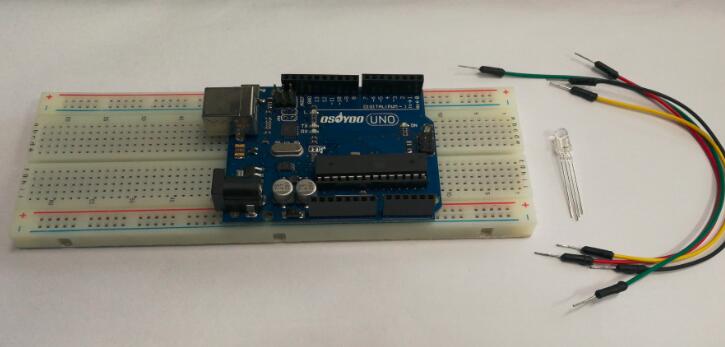
HARDWARE
- Osoyoo UNO Board (Fully compatible with Arduino UNO rev.3) x 1
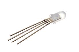
- RGB LED x 1
- 200 ohm Resistor x 3
- Potentiometer 10k x 3
- Breadboard x 1
- Jumpers
- USB Cable x 1
- PC x 1
Expanding Reading – About RGB LED
HOW DO RGB LEDS WORK?
At first glance, RGB (Red, Green, Blue) LEDs look just like regular LEDs, however, inside the usual LED package, there are actually three LEDs, one red, one green and yes, one blue. By controlling the brightness of each of the individual LEDs you can mix pretty much any color you want.
TWO TYPES OF RGB LEDS
There are common anode RGB LEDs and common cathode RGB LEDs. See figure below:
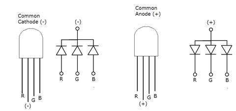
As you can see, the 3 LEDs can share the cathode or the anode. This results in an RGB LED that has 4 pins, one for each LED, and one common cathode or one common anode.
The 4 pins which can be distinguished by their length. The longest one is the ground (-) or voltage (+) depending if it is a common cathode or common anode LED, respectively.
The common anode RGB LED is the most popular type. We also use it here.
Note: If you are using a common ANODE LED instead of common CATHODE, connect the long pin to +5V instead of ground
HOW TO CREATE DIFFERENT COLORS?
The reason that you can mix any color you like by varying the quantities of red, green and blue light is that your eye has three types of light receptor in it (red, green and blue). Your eye and brain process the amounts of red, green and blue and convert it into a color of the spectrum.
In a way, by using the three LEDs we are playing a trick on the eye. This same idea is used in TVs, where the LCD has red, green and blue color dots next to each other making up each pixel.
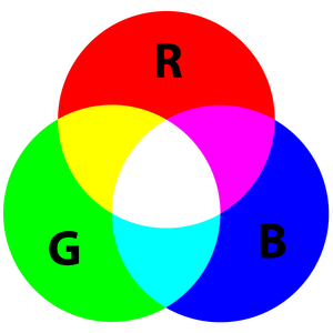
You can create one of those three colors – red, green or blue – by activating just one LED.
For example, if you want to produce blue, you activate the blue LED and turn off the other two.
If we set the brightness of all three LEDs to be the same, then the overall color of the light will be white. If we turn off the blue LED, so that just the red and green LEDs are the same brightness, then the light will appear yellow.
We can control the brightness of each of the red, green and blue parts of the LED separately, making it possible to mix any color we like.
Black is not so much a color as an absense of light. So the closest we can come to black with our LED is to turn off all three colors.
PULSE-WIDTH MODULATION(PWM)
The brightness of an LED is proportional to the current going through it, but it would be rather difficult to use a microcontroller to accurately control the current flowing through an LED. Fortunately, human vision has a nice phenomenon called persistence of vision. Persistence of vision is the phenomenon where an image that is seen for only a fraction of a second will continue to be “seen” by your brain even after the original image has vanished or moved. This this the same principle behind film and television, where a rapidly changing image tricks your brain into seeing continuous motion. By turning our LED on and off rapidly, we can trick the brain into seeing an “average” value of brightness based on the duty cycle of the driving PWM signal.
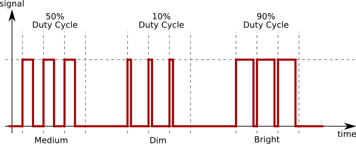
Pulse-width modulation (PWM) is the practice of modulating the duty cycle of a signal, used in this application to control the average power sent to each LED. In the following figure, we show three different duty cycles, first with 50% duty cycle, then 10% and 90% duty cycle. During the 10% duty cycle, the signal is at the logic high level for only a brief time each cycle, but with 90% duty cycle, most of the signal’s period is spent at logic high level. If the frequency of the signal is fast enough, then there will be no visible flicker, and the LED’s brightness will be proportional to the signal’s duty cycle.
Example
RGB LED COLOR CONTROL
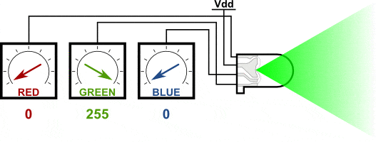
RGB stands for the red, green, and blue color channels and is an industry color standard. RGB displays various new colors by changing the three channels and superimposing them, which, according to statistics, can create 16,777,216 different colors. If you say the color displayed doesn’t completely match a natural color, then it almost certainly cannot be differentiated with the naked eyes.
Each of the three color channels of red, green, and blue has 255 stages of brightness. When the three primary colors are all 0, “LED light” is the darkest, that is, it turns off. When the three primary colors are all 255, “LED light” is the brightest. When superimposing the light emitted by the three primary colors, the colors will be mixed. However, the brightness is equal to the sum of all brightness, and the more you mix, the brighter the LED is. This process is known as additive mixing.
In this experiment, we will also use PWM which, if you’ve followed the lessons thus far, you already have a basic understanding of. Here we input a value between 0 and 255 to the three pins of the RGB LED to make it display different colors.

Connection
Build the circuit as below:
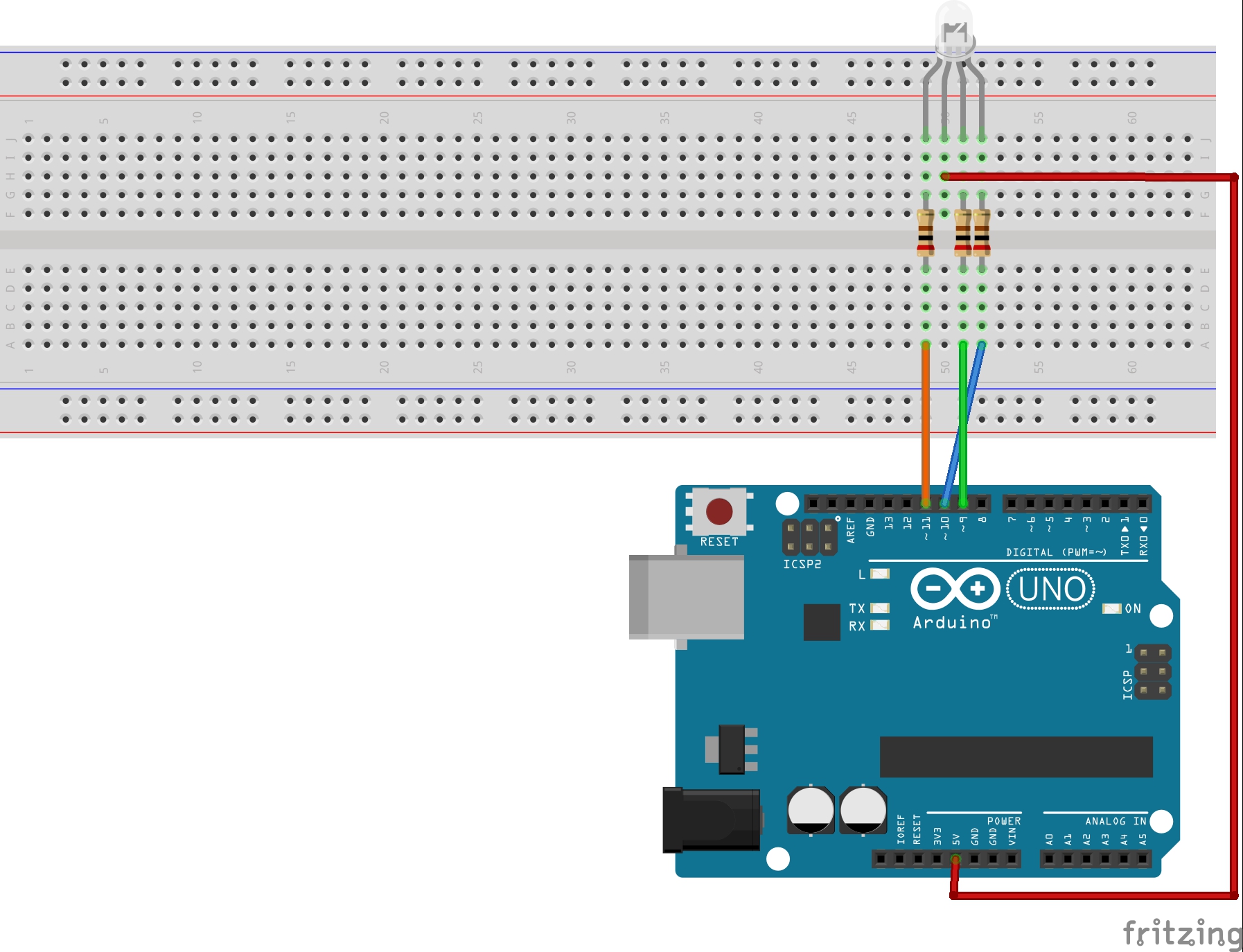
Each LED inside the package requires its own 200Ω resistor to prevent too much current flowing through it. The three positive leads of the LEDs (one red, one green and one blue) are connected to Arduino output pins using these resistors.
Code Program
After above operations are completed, connect the Arduino board to your computer using the USB cable. The green power LED (labelled PWR) should go on.Open the Mixly and choose corresponding board type and port type for you project.
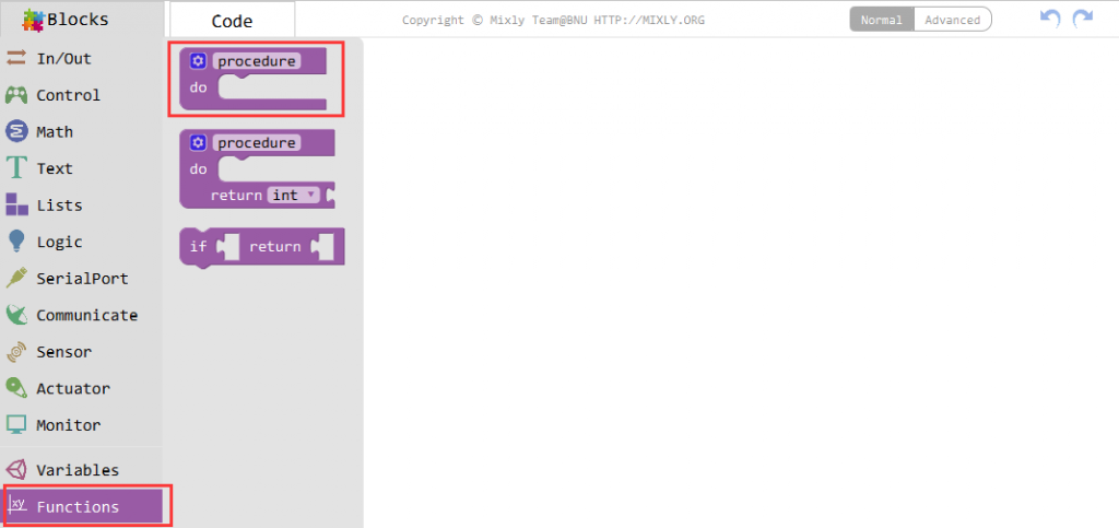
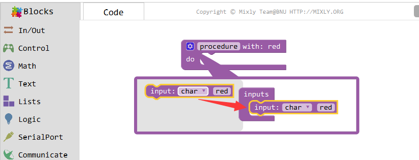
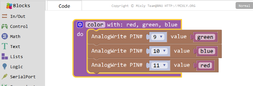
First we should build the user-defined function. Click the first block in Functions.
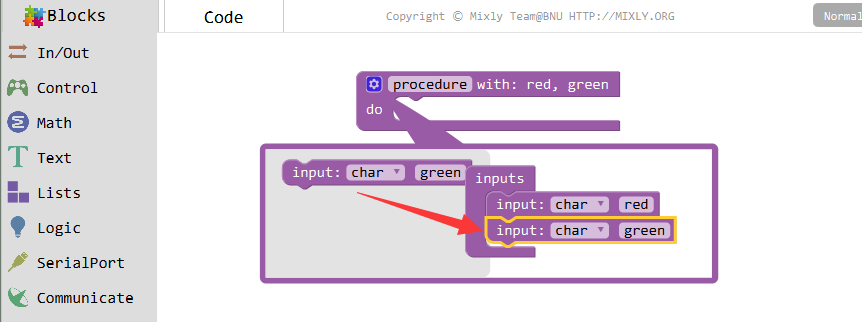
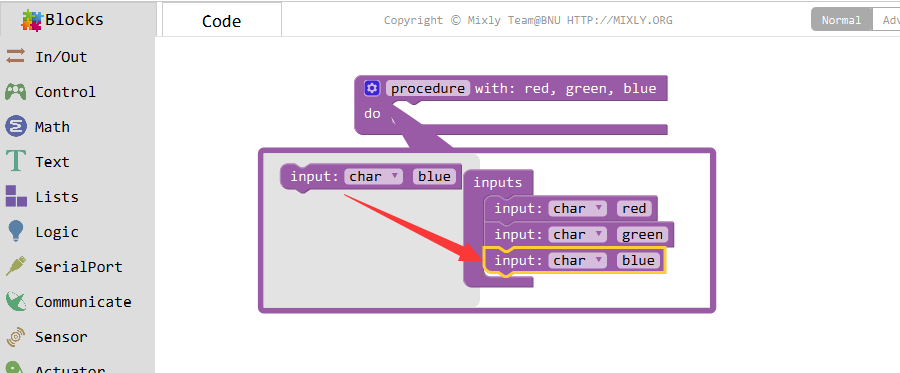
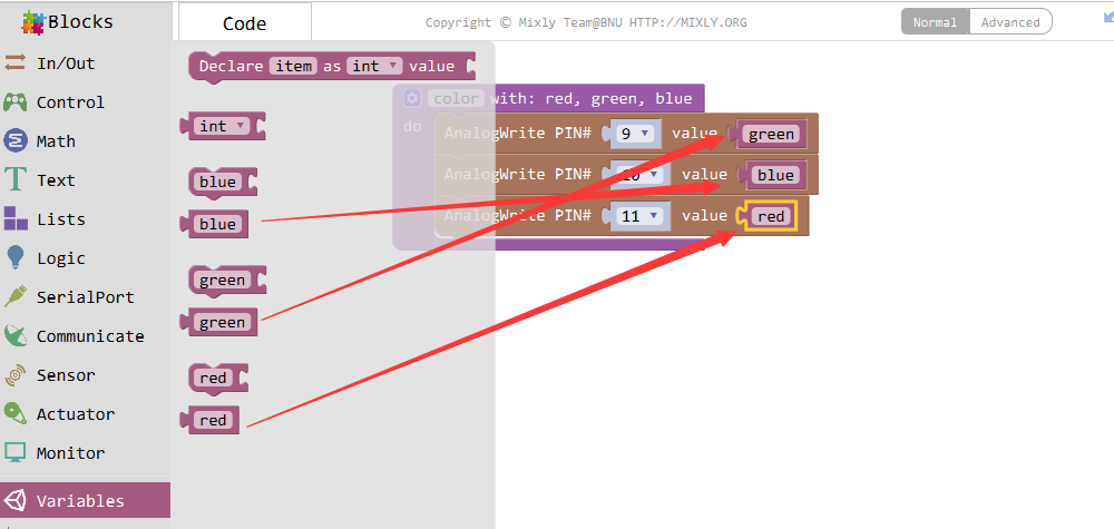
Click the setting icon, edit and drag red, green, and blue three char-type variables into the inputsblock on the right side.
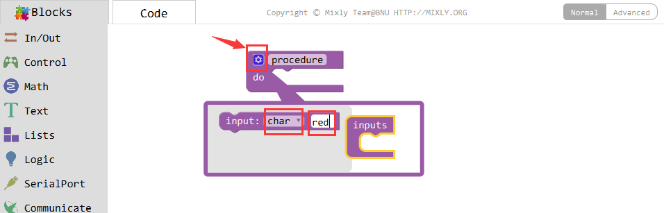
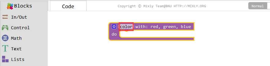
Click  again to fold the sub-block, modify the name of the function-better with clear indicatithus here change”procedure”to”color.
Drag out three Analog Write blocks inIn/Out. Then set pin 11 connected to RGB LEDS red pin, pi0 to green, while pin 9to blue. You can find those blocks in Variables.
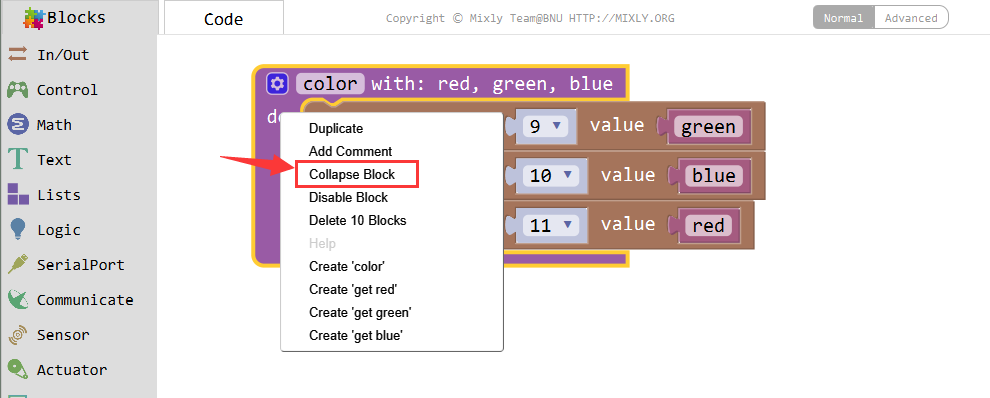
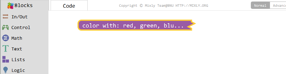
Right-click on the bulk, and click Collapse Block to fold it if it,’s too long.
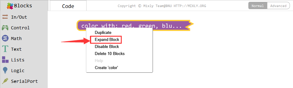
To unfold, right-click and click Expand Block.
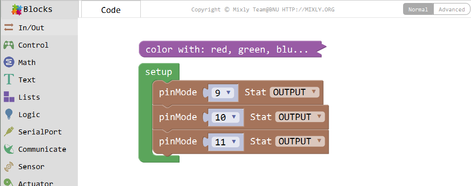
Then, drag out a setup block and three pinMode blocks in In/Out, and setup 9~11 as output.
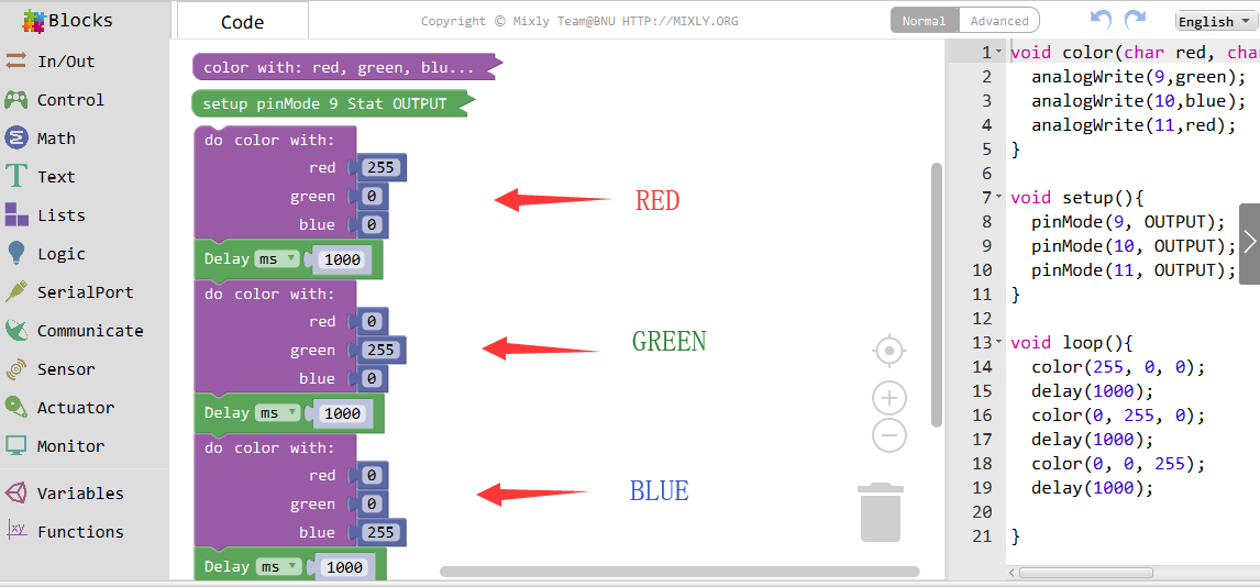
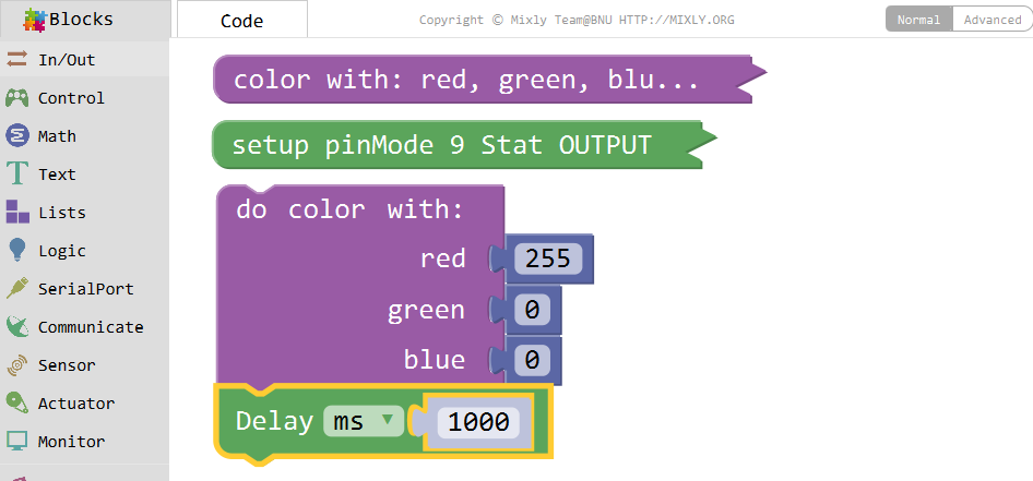
To build a loop function, drag out the fourth block do color with in Functions
Drag out the first block in Math three times and add them behind. Change the values of red, giand blue(that is to change the brightness value of R, G, and B respectively) to get various mixedcolors for the RGB LED.
Set the values for three as follows,

Add a Delay block of 1000ms, to keep one color value for 1s before changing into another.
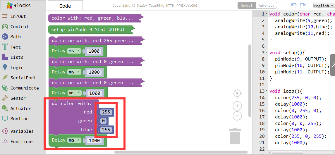
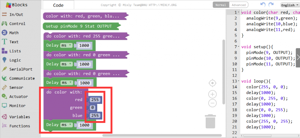
Combine different brightness values of R, G, and B, so we can get various mixed colors. You can setthe values as shown below(ranging from 0 to 255).

You can fold the bulks if they are too long. Then upload the program.
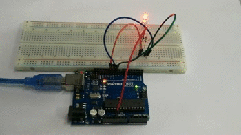
Running Result
A few seconds after the upload finishes, you should see the RGB LED flash circularly red, green, and blue first, then the RGB LED will display the corresponding color of the RGB value you added later.