This sensor is a carrier/breakout board for ST’s VL53L0X laser-ranging sensor, which measures the range to a target object up to 2 m away. The VL53L0X uses time-of-flight measurements of infrared pulses for ranging, allowing it to give accurate results independent of the target’s color and surface. Distance measurements can be read through a digital I²C interface. The board has a 2.8 V linear regulator and integrated level-shifters that allow it to work over an input voltage range of 2.6 V to 5.5 V, and the 0.1″ pin spacing makes it easy to use with standard solderless breadboards and 0.1″ perfboards.
Introduction
Time of Flight Distance Sensor-VL53L0X is a high speed, high accurary and long range distance sensor based on VL53L0X.
The VL53L0X is a new generation Time-of-Flight (ToF) laser-ranging module housed in the smallest package on the market today, providing accurate distance measurement whatever the target reflectances unlike conventional technologies. It can measure absolute distances up to 2m, setting a new benchmark in ranging performance levels, opening the door to various new applications.
The VL53L0X integrates a leading-edge SPAD array (Single Photon Avalanche Diodes) and embeds ST’s second generation FlightSenseTM patented technology.
The VL53L0X’s 940 nm VCSEL emitter (VerticalCavity Surface-Emitting Laser), is totally invisible to the human eye, coupled with internal physical infrared filters, it enables longer ranging distances, higher immunity to ambient light, and better robustness to cover glass optical crosstalk.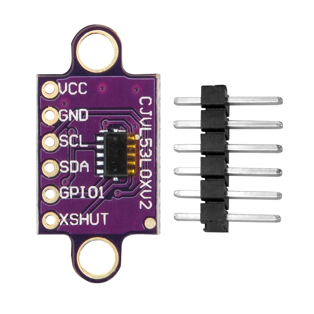 Hardware Overview
First let’s check out some of the characteristics of the VL53L1X sensor we’re dealing with, so we know what to expect out of the board.
| Characteristic |
Range |
| Operating Voltage |
2.6V-3.5V |
| Power Consumption |
20 mW @10Hz |
| Measurement Range |
~40mm to 4,000mm |
| Resolution |
+/-1mm |
| Light Source |
Class 1 940nm VCSEL |
| I2C Address |
0x29 |
| Field of View |
15° – 27° |
| Max Read Rate |
50Hz |
Specifications
- Dimensions: 0.5″ × 0.7″ × 0.085″ (13 mm × 18 mm × 2 mm)
- Weight without header pins: 0.5 g (0.02 oz)
- Operating voltage: 2.6 V to 5.5 V
- Supply current: 10 mA (typical average during active ranging)
- Varies with configuration, target, and environment. Peak current can reach 40 mA.
- Output format (I²C): 16-bit distance reading (in millimeters)
- Distance measuring range: up to 2 m (6.6 ft); see the graph at the right for typical ranging performance.
- Effective range depends on configuration, target, and environment.
- The datasheet does not specify a minimum range, but in our experience, the effective limit is about 3 cm.
Pinout
| PIN |
Description |
| VDD |
Regulated 2.8 V output. Almost 150 mA is available to power external components. (If you want to bypass the internal regulator, you can instead use this pin as a 2.8 V input with VIN disconnected.) |
| VIN |
This is the main 2.6 V to 5.5 V power supply connection. The SCL and SDA level shifters pull the I²C lines high to this level. |
| GND |
The ground (0 V) connection for your power supply. Your I²C control source must also share a common ground with this board. |
| SDA |
Level-shifted I²C data line: HIGH is VIN, LOW is 0 V |
| SCL |
Level-shifted I²C clock line: HIGH is VIN, LOW is 0 V |
| XSHUT |
This pin is an active-low shutdown input; the board pulls it up to VDD to enable the sensor by default. Driving this pin low puts the sensor into hardware standby. This input is not level-shifted. |
| GPIO1 |
Programmable interrupt output (VDD logic level). This output is not level-shifted. |
Schematic diagram
The above schematic shows the additional components the carrier board incorporates to make the VL53L0 easier to use, including the voltage regulator that allows the board to be powered from a 2.6 V to 5.5 V supply and the level-shifter circuit that allows for I²C communication at the same logic voltage level as VIN. This schematic is also available as a downloadable PDF (110k pdf).
Applications
- User detection for personal computers/laptops/tablets and IoT (energy saving)
- Robotics (obstacle detection)
- White goods (hand detection in automatic faucets, soap dispensers etc.)
- 1D gesture recognition.
- Laser assisted autofocus. Enhances and speeds up camera autofocus system performance, especially in difficult scenes (low light levels, low contrast) or fast moving video mode.
Getting started with VL53L0X
in this tutorial we are going to see how to interface the VL53L0X sensor with arduino. The VL53L0X is a I2C sensor. That means it uses the two I2C data/clock wires available on most microcontrollers, and can share those pins with other sensors as long as they don’t have an address collision.The VL53L0X is a Time of Flight distance sensor like no other you’ve used! The sensor contains a very tiny invisible laser source, and a matching sensor. let’s start our tutorial
Step1: Hardware required
- Arduino Board
- VL53L0x module
- jumper wires
Step2: Connecting the Hardware
- Connect Vin to the power supply, 3-5V is fine. Use the same voltage that the microcontroller logic is based off of. For most Arduinos, that is 5V
- Connect GND to common power/data ground
- Connect the SCL pin to the I2C clock SCL pin on your Arduino. On an UNO & ‘328 based Arduino, this is also known as A5, on a Mega it is also known as digital 21 and on a Leonardo/Micro, digital 3
- Connect the SDA pin to the I2C data SDA pin on your Arduino. On an UNO & ‘328 based Arduino, this is also known as A4, on a Mega it is also known as digital 20 and on a Leonardo/Micro, digital 2
As shown below

Download Adafruit_VL53L0X
To begin reading sensor data, you will need to install theAdafruit_VL53L0X Library.
The easiest way to do that is to open up the Manage Libraries…menu in the Arduino IDE
Then search for Adafruit VL53L0X and click Install
Load Demo
Open up File->Examples->Adafruit_VL53L0X->vl53l0x and upload to your Arduino wired up to the sensor
Thats it! Now open up the serial terminal window at 115200 speed to begin the test.
Move your hand up and down to read the sensor data. Note that when nothing is detected, it will say the reading is out of range
Don’t forget to remove the protective plastic cover from the sensor before using!
Connecting Multiple Sensors
I2C only allows one address-per-device so you have to make sure each I2C device has a unique address. The default address for the VL53L0X is 0x29 but you can change this in software.
To set the new address you can do it one of two ways. During initialization, instead of calling lox.begin(), call lox.begin(0x30)to set the address to 0x30. Or you can, later, call lox.setAddress(0x30) at any time.
The good news is its easy to change, the annoying part is each other sensor has to be in shutdown. You can shutdown each sensor by wiring up to the XSHUT pin to a microcontroller pin. Then perform something like this pseudo-code:
- Reset all sensors by setting all of their XSHUT pins low for delay(10), then set all XSHUT high to bring out of reset
- Keep sensor #1 awake by keeping XSHUT pin high
- Put all other sensors into shutdown by pulling XSHUT pins low
- Initialize sensor #1 with lox.begin(new_i2c_address) Pick any number but 0x29 and it must be under 0x7F. Going with 0x30 to 0x3F is probably OK.
- Keep sensor #1 awake, and now bring sensor #2 out of reset by setting its XSHUT pin high.
- Initialize sensor #2 with lox.begin(new_i2c_address) Pick any number but 0x29 and whatever you set the first sensor to
- Repeat for each sensor, turning each one on, setting a unique address.
Note you must do this every time you turn on the power, the addresses are not permanent!


