Note: ALL OSOYOO Products for Arduino are Third Party Board which is fully compatitable with Arduino
Authorized Online Retailers:
Content
- Introduction
- Preparations
- About the button
- Connection
- Upload Sketch
- Program Running Result
- The Expansion Example
Introduction
In this lesson, we will show how to turn on/off an LED by using an I/O port and a button. The “I/O port” refers to the INPUT and OUTPUT port. Here the INPUT port of the Osoyoo Basic board is used to read the output of an external device. Since the board itself has an LED (connected to Pin 13), so you can use this LED to do this experiment for convenience.
Preparations
Hardware
- OSOYOO Basic Board (Fully compatible with Arduino UNO rev.3) x 1
- Breadboard x 1
- Switch Button x 1
- 10k ohm resistor x 1
- M/M jumpers
- USB Cable x 1
- PC x 1
Software
Arduino IDE (version 1.6.4+)
About the button
Buttons are a common component used to control electronic devices. They are usually used as switches to connect or disconnect circuits. Although buttons come in a variety of sizes and shapes, the one used here is a 12mm medium-size button as shown in the following pictures.

The little button that are used in this lesson have four connections, which can be a little confusing.
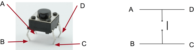
Actually, there are only really two electrical connections, as inside the switch package pins B and C are connected together, as are A and D.
Connection
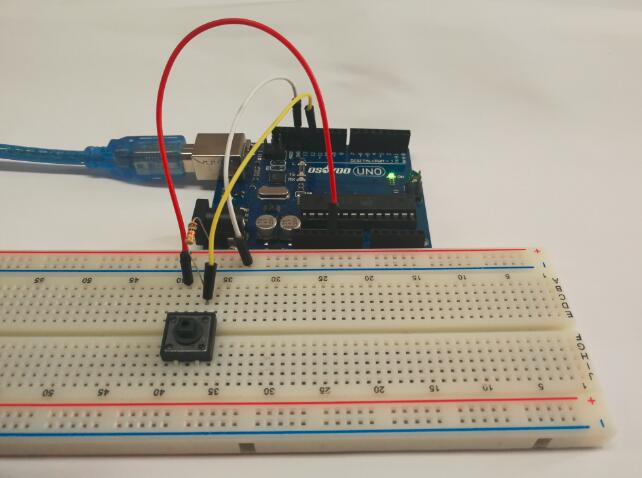
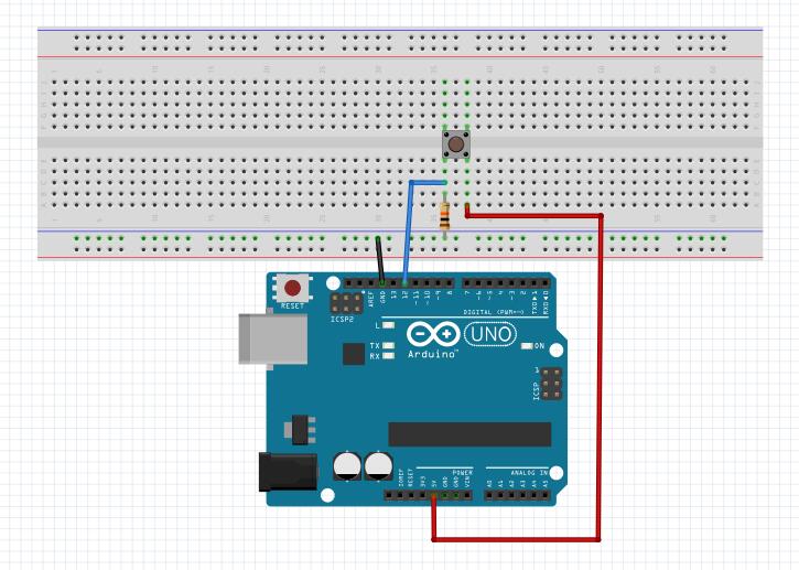
Although the bodies of the switches are square, the pins protrude from opposite sides of the switch. This means that the pins will only be far enough apart when they are the correct way around on the breadboard.Build the circuit as below:
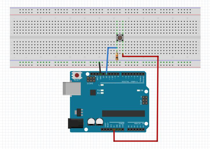
Notice:
Generally, the button is directly connected in an LED circuit in order to turn on or off the LED. This connection is relatively simple. However, sometimes the LED will light up automatically without pressing the button, which is caused by various interferences. In order to avoid these external interferences, a pull-down resistor is used, that is, to connect a 1K–10KΩ resistor between the button port and GND. It is used to consume external interferences while connected to GND for as long as the button switch is turned off.
Upload Sketch
After above operations are completed, connect the OSOYOO Basic Board to your computer using the USB cable. The green power LED (labelled PWR) should go on.
Code Program
You can download the sketch from this link or copy below code to your Arduino IDE window:
const int keyPin = 12; //the number of the key pin const int ledPin = 13;//the number of the led pin void setup() { pinMode(keyPin,INPUT);//initialize the key pin as input pinMode(ledPin,OUTPUT);//initialize the led pin as output } void loop() { //read the state of the key value //and check if the kye is pressed //if it is,the state is HIGH if(digitalRead(keyPin) ==HIGH ) { digitalWrite(ledPin,HIGH);//press the button to turn on the led } else { digitalWrite(ledPin,LOW);//release the button to turn off the led } }
Compile and upload
Open the Arduino IDE and select corresponding board type and port type for your OSOYOO Basic Board .

Now, simply click the “Upload” button in the environment. Wait a few seconds – you should see the RX and TX leds on the board flashing. If the upload is successful, the message “Done uploading.” will appear in the status bar.
Running Result
A few seconds after the upload finishes,when the button switch is pressed, LED light up; when the switch is released, the LED goes out.
The Expansion Example
After the routine above done, you might think, if we want to turn on the LED in this way, the hand cannot leave button, it is not convenient.How to control the lights as normal , click on the light, then press out? We can improve the program, which can realize the result that will modify the program for the following code, and then upload to the OSOYOO Basic Board.
The circuit is same as above,you can get the sketch from this link or copy below code to your new Arduino IDE window and upload it to your OSOYOO Basic Board . Don’t forget to choose the corresponding board and port for you project!
#define LED 13 // Set D13 as the LED pin #define BUTTON 12 //Set D12 as the button pin //Let's say you have your push button on pin 12 int switchState = 0; // actual read value from pin12 int oldSwitchState = 0; // last read value from pin12 int lightsOn = 0; // is the switch on = 1 or off = 0 void setup() { pinMode(BUTTON, INPUT); // set the push button as input pinMode(LED, OUTPUT); // anything you want to control using a switch e.g. a Led } void loop() { switchState = digitalRead(BUTTON); // read the pushButton State if (switchState != oldSwitchState) // catch change { oldSwitchState = switchState; if (switchState == HIGH) { // toggle lightsOn = !lightsOn; } } if(lightsOn) { digitalWrite(LED, HIGH); // set the LED on } else { digitalWrite(LED, LOW); // set the LED off } }
After the program is compiled and uploaded, you can achieve: click the button to turn on the LED, and then press this button, the LED will be turned off.