Note: ALL OSOYOO Products for Arduino are Third Party Board which is fully compatitable with Arduino
Authorized Online Retailers:
Content
- Introduction
- Preparations
- About the Stepper Motor
- Connection
- Upload Sketch
- Program Running Result
Introduction
This was written for the purpose of familiarizing you with stepper motors and subsequently how to program their operation into Arduino. Arduin is a prototyping program that allows the hobbyist or student level user to perform operations of more advanced circuits or microchips through the use of an easy to use and modular computer code. Though the code is simple it can still be challenging to many who are not familiar with computer code or the devices that a computer code can control.
A stepper motor, much like a DC motor has a rotating permanent magnet propelled by stationary electrical magnets, however the motion is divided into a number of steps around the rotation of the rotating magnet. It does so by having several teeth on the rotating magnet that line up with specific locations around the stationary charged magnets. When voltage is supplied to a specific magnet or specific sequence of magnets the motor will rotate, or step to that position and hold.
Stepper motors can spin like a regular DC motor, however they can also stop on a position like a servo motor. This gives them many uses. Some basic places where you will find stepper motors are in disc drives, printers, faxes, slot machines, clocks, intelligent lighting, and automotive gauges.
Preparations
Hardware
Software
- Arduino IDE (version 1.6.4+)
About the Stepper Motor
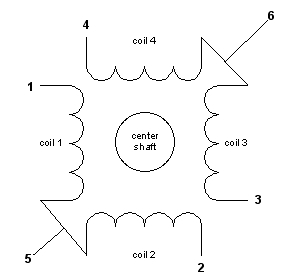
Stepper Motor is a motor controlled by a series of electromagnetic coils. The center shaft has a series of magnets mounted on it, and the coils surrounding the shaft are alternately given current or not, creating magnetic fields which repulse or attract the magnets on the shaft, causing the motor to rotate.
This design allows for very precious control of the motor,There are two basic types of stepper motors, unipolar steppers and bipolar steppers .
In this lesson, we will talk about an Unipolar Stepper Motor 28-BYJ48 .
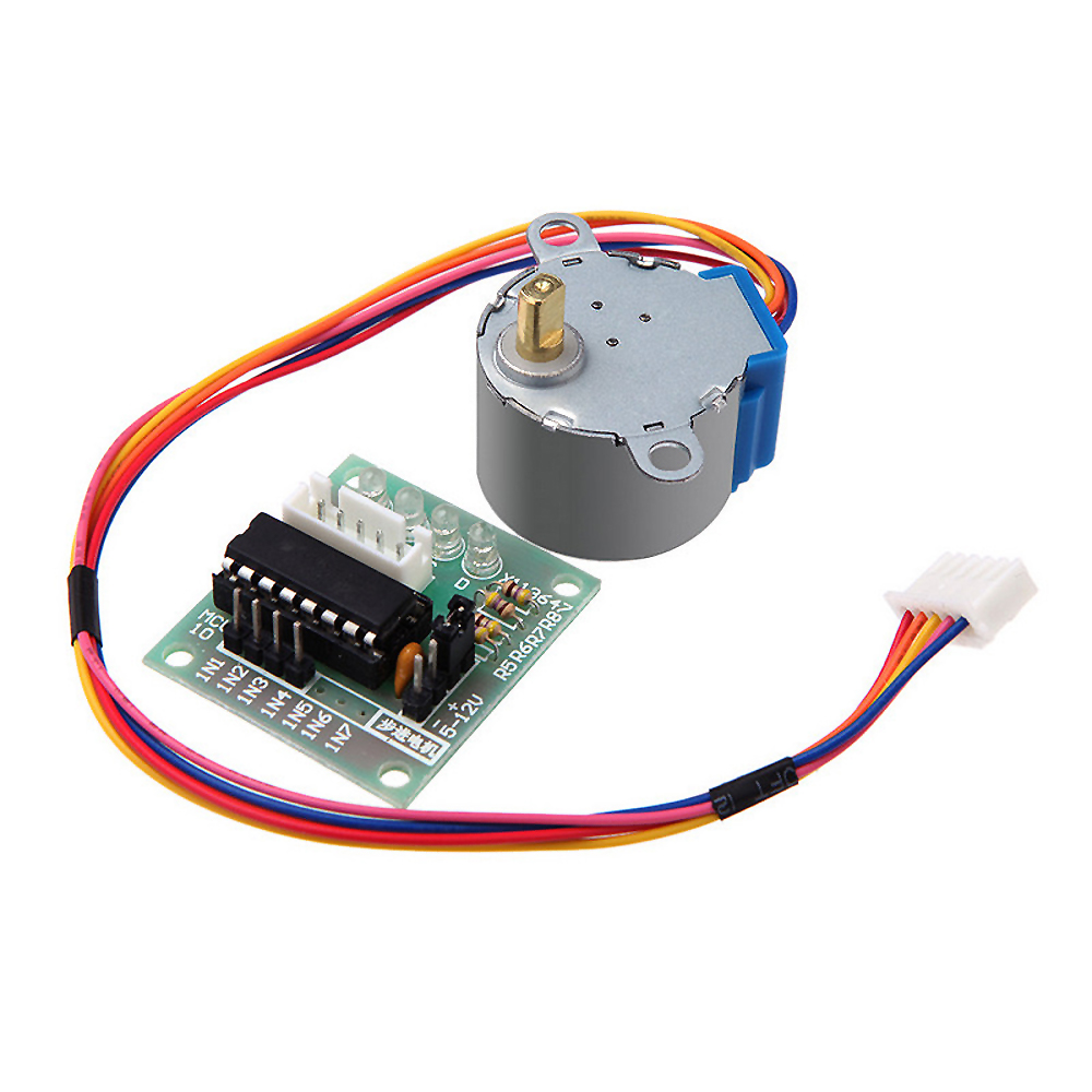
Unipolar Stepper Motors
The unipolar stepper motor has five or six wires and four coils (actually two coils divided by center connections on each coil). The center connections of the coils are tied together and used as the power connection. They are called unipolar steppers because power always comes in on this one pole. You can get the 28-BYJ48 motor datasheet here.
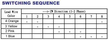
The simplest way of interfacing a unipolar stepper to Arduin is to use a breakout for ULN2003A transistor array chip. The ULN2003A contains seven darlington transistor drivers and is somewhat like having seven TIP120 transistors all in one package. The ULN2003A can pass up to 500 mA per channel and has an internal voltage drop of about 1V when on. It also contains internal clamp diodes to dissipate voltage spikes when driving inductive loads.To control the stepper, apply voltage to each of the coils in a specific sequence.
Here are schematics showing how to interface a unipolar stepper motor to four controller pins using a ULN2003A, and showing how to interface using four TIP120’s. Here is the datasheet of ULN2003.
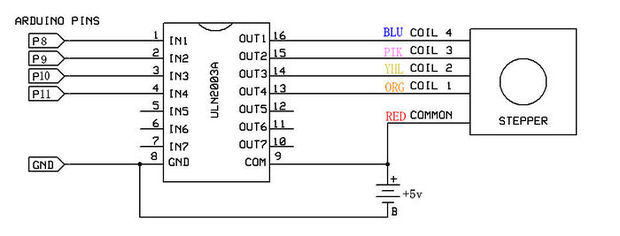
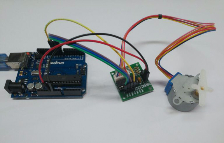
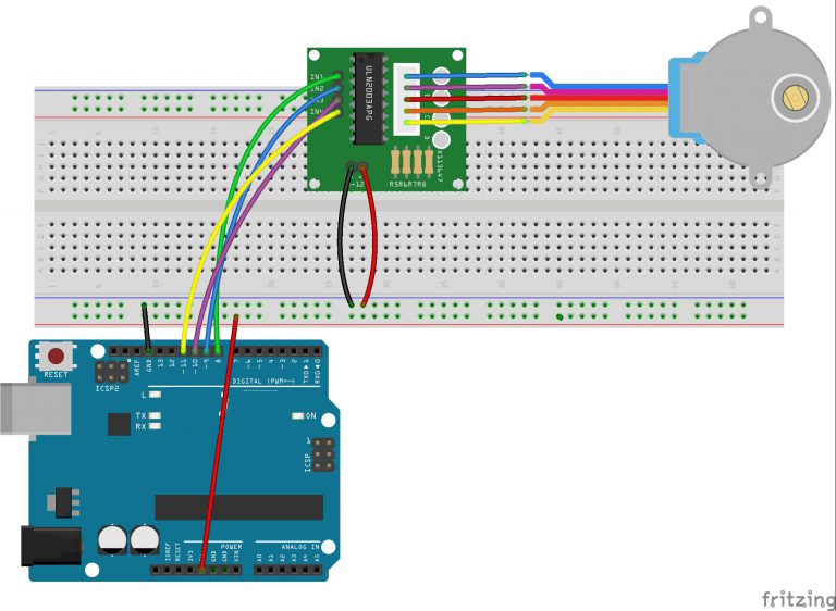
Connection
The wiring between Stepper Motor Driver board and Osoyoo basic board:
| Stepper Motor Driver |
Osoyoo basic |
| IN1 |
8 |
| IN2 |
9 |
| IN3 |
10 |
| IN4 |
11 |
| GND |
GND |
| VCC |
5V |
Notice: It is better to power your stepper motors from an external supply with 5V-500mA at least, as people draw too much to be powered directly from your board.
Upload Sketch
After above operations are completed, connect the board to your computer using the USB cable. The green power LED (labelled PWR) should go on.
Code Program
Copy the example code below into an program.
#define IN1 8
#define IN2 9
#define IN3 10
#define IN4 11
int Steps = 0;
boolean Direction = true;// gre
unsigned long last_time;
unsigned long currentMillis ;
int steps_left=4095;
long time;
void setup() {
Serial.begin(115200);
pinMode(IN1, OUTPUT);
pinMode(IN2, OUTPUT);
pinMode(IN3, OUTPUT);
pinMode(IN4, OUTPUT);
// delay(1000);
}
void loop() {
while(steps_left>0){
currentMillis = micros();
if(currentMillis-last_time>=1000){
stepper(1);
time=time+micros()-last_time;
last_time=micros();
steps_left--;
}
}
Serial.println(time);
Serial.println("Wait...!");
delay(2000);
Direction=!Direction;
steps_left=4095;
}

void stepper(int xw){
for (int x=0;x<xw;x++){
switch(Steps){
case 0:
digitalWrite(IN1, LOW);
digitalWrite(IN2, LOW);
digitalWrite(IN3, LOW);
digitalWrite(IN4, HIGH);
break;
case 1:
digitalWrite(IN1, LOW);
digitalWrite(IN2, LOW);
digitalWrite(IN3, HIGH);
digitalWrite(IN4, HIGH);
break;
case 2:
digitalWrite(IN1, LOW);
digitalWrite(IN2, LOW);
digitalWrite(IN3, HIGH);
digitalWrite(IN4, LOW);
break;
case 3:
digitalWrite(IN1, LOW);
digitalWrite(IN2, HIGH);
digitalWrite(IN3, HIGH);
digitalWrite(IN4, LOW);
break;
case 4:
digitalWrite(IN1, LOW);
digitalWrite(IN2, HIGH);
digitalWrite(IN3, LOW);
digitalWrite(IN4, LOW);
break;
case 5:
digitalWrite(IN1, HIGH);
digitalWrite(IN2, HIGH);
digitalWrite(IN3, LOW);
digitalWrite(IN4, LOW);
break;
case 6:
digitalWrite(IN1, HIGH);
digitalWrite(IN2, LOW);
digitalWrite(IN3, LOW);
digitalWrite(IN4, LOW);
break;
case 7:
digitalWrite(IN1, HIGH);
digitalWrite(IN2, LOW);
digitalWrite(IN3, LOW);
digitalWrite(IN4, HIGH);
break;
default:
digitalWrite(IN1, LOW);
digitalWrite(IN2, LOW);
digitalWrite(IN3, LOW);
digitalWrite(IN4, LOW);
break;
}
SetDirection();
}
}
void SetDirection(){
if(Direction==1){
Steps++;
}
if(Direction==0){
Steps--;
}
if(Steps>7){
Steps=0;
}
if(Steps<0){
Steps=7;
}
}
Compile and upload
Open the Arduino IDE and select corresponding board type and port type for your board.
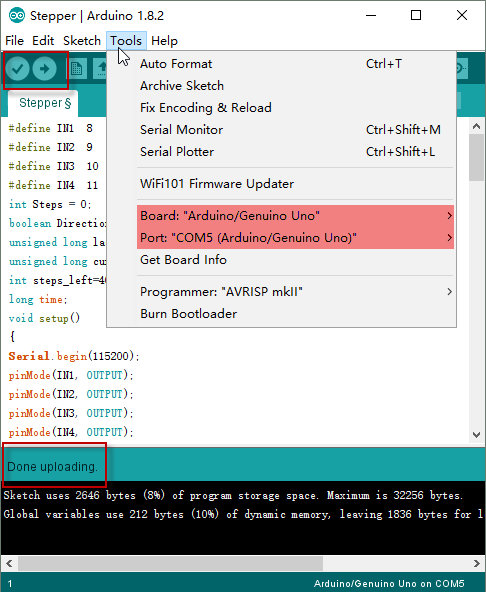
After compile this sketch, simply click the “Upload” button in the environment. Wait a few seconds – you should see the RX and TX leds on the board flashing. If the upload is successful, the message “Done uploading.” will appear in the status bar.
Running Result
A few seconds after the upload finishes, you should now see the motor turn the shaft one revolution clockwise and one counterclockwise.


