Note: ALL OSOYOO Products for Arduino are Third Party Board which is fully compatitable with Arduino
Content
- Introduction
- Preparations
- About the Hall Effect Sensor module
- Example
- Connection
- Upload Sketch
- Program Running Result
Introduction
The Hall Effect Sensor Module can be used to detect the presence of an magnetic field. If there is an magnetic field present, it will report a high level signal. It can be used in many applications such as RPM sensor (for counting the number of shaft revolutions), Robot speed and distance measurements, door switch and robot arm position sensor. Generally, it can be used for any magnetic field detection.
In this lesson we will learn how a Hall Effect Sensor Module works and how to use it with the Board for detecting magnetic.
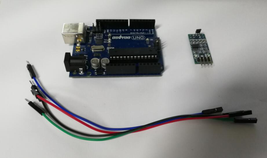
Preparations
Hardware
- Osoyoo UNO Board (Fully compatible with Arduino UNO rev.3) x 1
- Hall Effect Sensor Module x 1
- Relay x 1
- Breadboard x 1
- Jumpers
- USB Cable x 1
- PC x 1
Software
- Arduino IDE (version 1.6.4+)
About Hall Effect Sensor Module
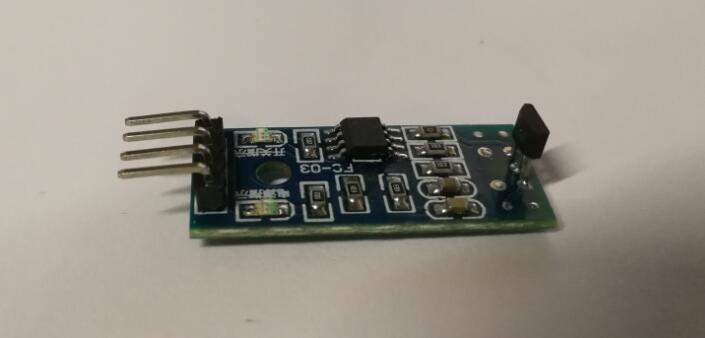
Overview
Hall Effect Sensors Module are devices which are activated by an external magnetic field. We know that a magnetic field has two important characteristics flux density, (B) and polarity (North and South Poles). The output signal from a Hall effect sensor is the function of magnetic field density around the device. When the magnetic flux density around the sensor exceeds a certain pre-set threshold, the sensor detects it and generates an output voltage called the Hall Voltage, VH .
Features
- S49E hall sensor
- Features wide range voltage comparator LM393
- Adjustable sensitivity (potentiometer)
- Signal output indicator
- Analog / Digital output
Specifications
- Volt: 2.3V ~ 5.3V
- Dimension: 27.0mm * 15.5mm
- Mounting holes size: 2.0mm
Hall Effect Sensor Principles
Hall Effect Sensors consist basically of a thin piece of rectangular p-type semiconductor material such as gallium arsenide (GaAs), indium antimonide (InSb) or indium arsenide (InAs) passing a continuous current through itself. When the device is placed within a magnetic field, the magnetic flux lines exert a force on the semiconductor material which deflects the charge carriers, electrons and holes, to either side of the semiconductor slab. This movement of charge carriers is a result of the magnetic force they experience passing through the semiconductor material.
As these electrons and holes move side wards a potential difference is produced between the two sides of the semiconductor material by the build-up of these charge carriers. Then the movement of electrons through the semiconductor material is affected by the presence of an external magnetic field which is at right angles to it and this effect is greater in a flat rectangular shaped material.
The effect of generating a measurable voltage by using a magnetic field is called the Hall Effect after Edwin Hall who discovered it back in the 1870’s with the basic physical principle underlying the Hall effect being Lorentz force. To generate a potential difference across the device the magnetic flux lines must be perpendicular, (90o) to the flow of current and be of the correct polarity, generally a south pole.
The Hall effect provides information regarding the type of magnetic pole and magnitude of the magnetic field. For example, a south pole would cause the device to produce a voltage output while a north pole would have no effect. Generally, Hall Effect sensors and switches are designed to be in the “OFF”, (open circuit condition) when there is no magnetic field present. They only turn “ON”, (closed circuit condition) when subjected to a magnetic field of sufficient strength and polarity.
Hall Effect Magnetic Sensor
The output voltage, called the Hall voltage, (VH) of the basic Hall Element is directly proportional to the strength of the magnetic field passing through the semiconductor material (output ∝ H). This output voltage can be quite small, only a few microvolts even when subjected to strong magnetic fields so most commercially available Hall effect devices are manufactured with built-in DC amplifiers, logic switching circuits and voltage regulators to improve the sensors sensitivity, hysteresis and output voltage. This also allows the Hall effect sensor to operate over a wider range of power supplies and magnetic field conditions.
The Hall Effect Sensor
Hall Effect Sensors are available with either linear or digital outputs. The output signal for linear (analogue) sensors is taken directly from the output of the operational amplifier with the output voltage being directly proportional to the magnetic field passing through the Hall sensor. This output Hall voltage is given as:
- Where:
- VH is the Hall Voltage in volts
- RH is the Hall Effect co-efficient
- I is the current flow through the sensor in amps
- t is the thickness of the sensor in mm
- B is the Magnetic Flux density in Teslas
|
 |
Linear or analogue sensors give a continuous voltage output that increases with a strong magnetic field and decreases with a weak magnetic field. In linear output Hall effect sensors, as the strength of the magnetic field increases the output signal from the amplifier will also increase until it begins to saturate by the limits imposed on it by the power supply. Any additional increase in the magnetic field will have no effect on the output but drive it more into saturation.
Digital output sensors on the other hand have a Schmitt-trigger with built in hysteresis connected to the op-amp. When the magnetic flux passing through the Hall sensor exceeds a pre-set value the output from the device switches quickly between its “OFF” condition to an “ON” condition without any type of contact bounce. This built-in hysteresis eliminates any oscillation of the output signal as the sensor moves in and out of the magnetic field. Then digital output sensors have just two states, “ON” and “OFF”.
There are two basic types of digital Hall effect sensor, Bipolar and Unipolar. Bipolar sensors require a positive magnetic field (south pole) to operate them and a negative field (north pole) to release them while unipolar sensors require only a single magnetic south pole to both operate and release them as they move in and out of the magnetic field.
Most Hall effect devices can not directly switch large electrical loads as their output drive capabilities are very small around 10 to 20mA. For large current loads an open-collector (current sinking) NPN Transistor is added to the output.
This transistor operates in its saturated region as a NPN sink switch which shorts the output terminal to ground whenever the applied flux density is higher than that of the “ON” pre-set point.
The output switching transistor can be either an open emitter transistor, open collector transistor configuration or both providing a push-pull output type configuration that can sink enough current to directly drive many loads, including relays, motors, LEDs, and lamps.
Hall Effect Applications
Hall effect sensors are activated by a magnetic field and in many applications the device can be operated by a single permanent magnet attached to a moving shaft or device. There are many different types of magnet movements, such as “Head-on”, “Sideways”, “Push-pull” or “Push-push” etc sensing movements. Which every type of configuration is used, to ensure maximum sensitivity the magnetic lines of flux must always be perpendicular to the sensing area of the device and must be of the correct polarity.
Also to ensure linearity, high field strength magnets are required that produce a large change in field strength for the required movement. There are several possible paths of motion for detecting a magnetic field, and below are two of the more common sensing configurations using a single magnet: Head-on Detection and Sideways Detection.
Head-on Detection
As its name implies, “head-on detection” requires that the magnetic field is perpendicular to the hall effect sensing device and that for detection, it approaches the sensor straight on towards the active face. A sort of “head-on” approach.
This head-on approach generates an output signal, VH which in the linear devices represents the strength of the magnetic field, the magnetic flux density, as a function of distance away from the hall effect sensor. The nearer and therefore the stronger the magnetic field, the greater the output voltage and vice versa.
Linear devices can also differentiate between positive and negative magnetic fields. Non-linear devices can be made to trigger the output “ON” at a pre-set air gap distance away from the magnet for indicating positional detection.
Sideways Detection
The second sensing configuration is “sideways detection”. This requires moving the magnet across the face of the Hall effect element in a sideways motion.
Sideways or slide-by detection is useful for detecting the presence of a magnetic field as it moves across the face of the Hall element within a fixed air gap distance for example, counting rotational magnets or the speed of rotation of motors.
Depending upon the position of the magnetic field as it passes by the zero field centre line of the sensor, a linear output voltage representing both a positive and a negative output can be produced. This allows for directional movement detection which can be vertical as well as horizontal.
There are many different applications for Hall Effect Sensors especially as proximity sensors. They can be used instead of optical and light sensors were the environmental conditions consist of water, vibration, dirt or oil such as in automotive applications. Hall effect devices can also be used for current sensing.
We know from the previous tutorials that when a current passes through a conductor, a circular electromagnetic field is produced around it. By placing the Hall sensor next to the conductor, electrical currents from a few milliamps into thousands of amperes can be measured from the generated magnetic field without the need of large or expensive transformers and coils.
As well as detecting the presence or absence of magnets and magnetic fields, Hall effect sensors can also be used to detect ferromagnetic materials such as iron and steel by placing a small permanent “biasing” magnet behind the active area of the device. The sensor now sits in a permanent and static magnetic field, and any change or disturbance to this magnetic field by the introduction of a ferrous material will be detected with sensitivities as low as mV/G possible.
There are many different ways to interface Hall effect sensors to electrical and electronic circuits depending upon the type of device, whether digital or linear. One very simple and easy to construct example is using a Light Emitting Diode as shown below.
Positional Detector
This head-on positional detector will be “OFF” when there is no magnetic field present, (0 gauss). When the permanent magnets south pole (positive gauss) is moved perpendicular towards the active area of the Hall effect sensor the device turns “ON” and lights the LED. Once switched “ON” the Hall effect sensor stays “ON”.
To turn the device and therefore the LED “OFF” the magnetic field must be reduced to below the release point for unipolar sensors or exposed to a magnetic north pole (negative gauss) for bipolar sensors. The LED can be replaced with a larger power transistor if the output of the Hall Effect Sensor is required to switch larger current loads.
Examples
Hall Effect Sensors Module Basic Example
In this example, we are going to use a hall effect sensor module to turn the Osoyoo UNO’s built-in led on and off with a magnet.
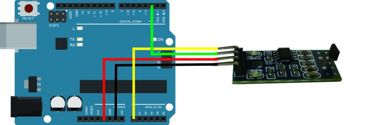
Connection
Build the circuit as below:
Code Program
After above operations are completed, connect the board to your computer using the USB cable. The green power LED (labelled PWR) should go on.Open the Arduino IDE and choose corresponding board type and port type for you project. Then load up the following sketch onto your board.
const int ledPin = 13;//the led attach to pin13
int sensorPin = A0; // select the input pin for the potentiometer
int digitalPin=2; //D0 attach to pin2
int sensorValue = 0;// variable to store the value coming from A0
boolean digitalValue=0;// variable to store the value coming from pin2
void setup()
{
  pinMode(digitalPin,INPUT);//set the state of D0 as INPUT
  pinMode(ledPin,OUTPUT);//set the state of pin13 as OUTPUT
  Serial.begin(9600); // initialize serial communications at 9600 bps
}
void loop()
{
  sensorValue = analogRead(sensorPin); //read the value of A0
  digitalValue=digitalRead(digitalPin); //read the value of D0
  Serial.print("Sensor Value "); // print label to serial monitor
  Serial.println(sensorValue); //print the value of A0
  Serial.print("Digital Value "); // print label to serial monitor
  Serial.println(digitalValue); //print the value of D0 in the serial
  if( digitalValue==HIGH )//if the value of D0 is HIGH
  {
    digitalWrite(ledPin,LOW);//turn off the led
  }
  if( digitalValue==LOW)//else
  {
    digitalWrite(ledPin,HIGH);//turn on the led
  }
  delay(1000);//delay 200ms
}
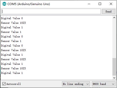
Running Result
A few seconds after the upload finishes, place a magnet close to the switch Hall sensor. Then the indicator LED on the switch Hall sensor will light up, at the same time, the LED attached to pin 13 on the Osoyoo Uno board will light up.
Open the Serial Monitor you will see the analog value and the digital value as below: