Note: ALL OSOYOO Products for Arduino are Third Party Board which is fully compatitable with Arduino
Content
- Introduction
- Preparations
- About the 2-Channel Relay Module
- Example
- Connection
- Upload Sketch
- Program Running Result
Introduction
A relay is an electrically operated switch. Many relays use an electromagnet to mechanically operate a switch, but other operating principles are also used, such as solid-state relays. Relays are used where it is necessary to control a circuit by a separate low-power signal, or where several circuits must be controlled by one signal.
In this lesson, we will show you how the 2-Channel Relay Module works and how to use it with the Osoyoo Uno board to control high voltage devices.
Preparations
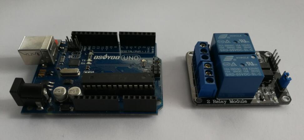
Hardware
- Osoyoo UNO Board (Fully compatible with Arduino UNO rev.3) x 1
- 2-Channel Relay Module x 1
- Breadboard x 1
- Jumpers
- USB Cable x 1
- PC x 1
Software
- Arduino IDE (version 1.6.4+)
About 2-Channel Relay Module
Overview
This is a 5V 2-Channel Relay Module board, Be able to control various appliances, and other equipment with large current. It can be controlled directly by Microcontroller (Raspberry Pi, Arduino, 8051, AVR, PIC, DSP, ARM, ARM, MSP430, TTL logic). Very useful project for application like Micro-Controller based projects, Remote controller, Lamp on Off, and any circuits which required isolated high current and high voltage switching by applying any TTL or CMOS level voltage.
Features
- High current relay, AC250V 10A, DC30V 10A
- 2 LEDs to indicate when relays are on
- Works with logic level signals from 3.3V or 5V devices
- Opto isolation circuitry
- PCB size: 50×45 mm
Pins Out
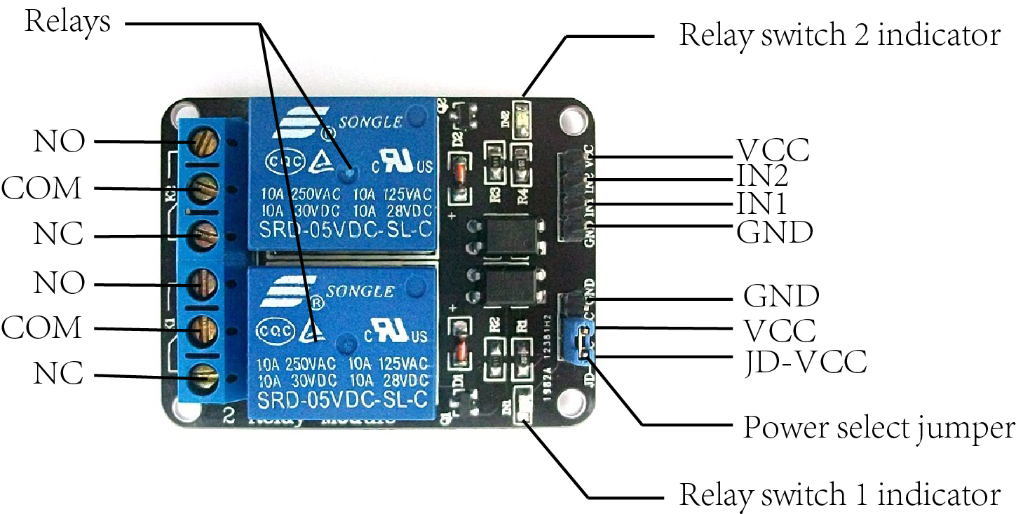
Input
It has a 1×4 (2.54mm pitch) pin header for connecting power (5V and 0V), and for controlling the 2 relays. The pins are marked on the PCB:
- GND – Connect 0V to this pin.
- IN1 – Controls relay 1, active Low! Relay will turn on when this input goes below about 2.0V
- IN2 – Controls relay 2, active Low! Relay will turn on when this input goes below about 2.0V
- VCC – Connect 5V to this pin. Is used to power the opto couplers
There is a second 1×3 (2.54mm pitch) pin header for supplying the “relay side” of the board with 5V. At delivery, a jumper is present on this header selecting the 5V signal from the 1×4 pin header to power the relays. For default operation, don’t change this jumper!
The pins of the 1×3 pin header are marked on the PCB:
- JD-VCC – This is the 5V required for the relays. At delivery, a jumper is present on this and the adjacent (VCC) pin.
- VCC – This is the 5V VCC supplied on the 1×4 pin connector
- GND – Connected to 0V pin of 1×4 pin header
If opto isolation is required, an isolated 5V supply should be used. For normal operation, a jumper bewtween pins 1 and 2 selects the 5V signal from the 1×4 pin header. This means both the “input side”, and “relay side” use the same 5V supply, and there is no opto-isolation.
Output
The 2 channel relay module could be considered like a series switches: 2 normally Open (NO), 2 normally closed (NC) and 2 common Pins (COM).
- COM- Common pin
- NC- Normally Closed, in which case NC is connected with COM when INT1 is set low and disconnected when INT1 is high
- NO- Normally Open, in which case NO is disconnected with COM1 when INT1 is set low and connected when INT1 is high
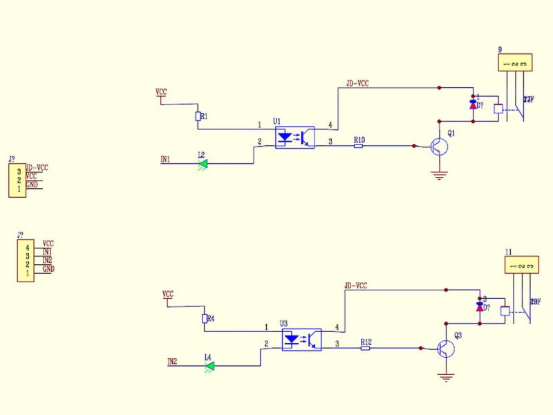
Schematic
How relay works?
The working of a relay can be better understood by explaining the following diagram given below.
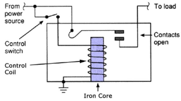
There are 5 parts in every relay:
1. Electromagnet – It consists of an iron core wounded by coil of wires. When electricity is passed through, it becomes magnetic. Therefore, it is called electromagnet.
2. Armature – The movable magnetic strip is known as armature. When current flows through them, the coil is it energized thus producing a magnetic field which is used to make or break the normally open (N/O) or normally close (N/C) points. And the armature can be moved with direct current (DC) as well as alternating current (AC).
3. Spring – When no currents flow through the coil on the electromagnet, the spring pulls the armature away so the circuit cannot be completed.
4. Set of electrical contacts – There are two contact points:
.Normally open – connected when the relay is activated, and disconnected when it is inactive.
.Normally close – not connected when the relay is activated, and connected when it is inactive.
5. Molded frame – Relays are covered with plastic for protection.
Principle
The diagram shows an inner section diagram of a relay. An iron core is surrounded by a control coil. As shown, the power source is given to the electromagnet through a control switch and through contacts to the load. When current starts flowing through the control coil, the electromagnet starts energizing and thus intensifies the magnetic field. Thus the upper contact arm starts to be attracted to the lower fixed arm and thus closes the contacts causing a short circuit for the power to the load. On the other hand, if the relay was already de-energized when the contacts were closed, then the contact move oppositely and make an open circuit.
As soon as the coil current is off, the movable armature will be returned by a force back to its initial position. This force will be almost equal to half the strength of the magnetic force. This force is mainly provided by two factors. They are the spring and also gravity.
Relays are mainly made for two basic operations. One is low voltage application and the other is high voltage. For low voltage applications, more preference will be given to reduce the noise of the whole circuit. For high voltage applications, they are mainly designed to reduce a phenomenon called arcing.
Before we continue with this lesson, I will warn you here that we will use High Voltage which if incorrectly or improperly used could result in serious injuries or death. So be very caution of what you are doing.

Examples
Using the board to Control a 2 Channel Relay
In this example, when a low level is supplied to signal terminal of the 2-channel relay, the LED on the relay will light up. Otherwise, it will turn off. If a periodic high and low level is supplied to the signal terminal, you can see the LED will cycle between on and off.
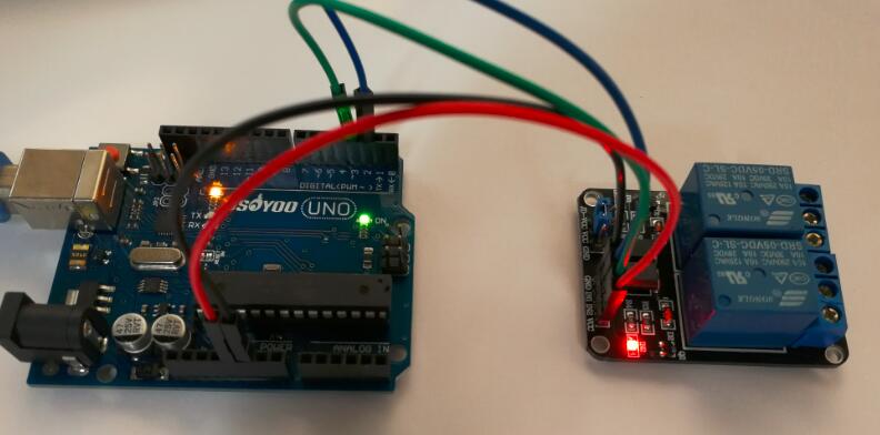
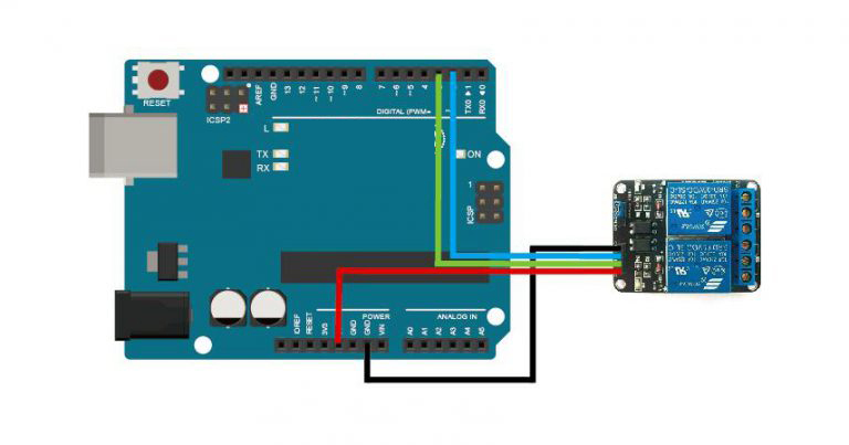
Connection
Build the circuit as below digram:
Code Program
After above operations are completed, connect the board to your computer using the USB cable. The green power LED (labelled PWR) should go on.Open the Arduino IDE and choose corresponding board type and port type for you project. Then load up the following sketch onto your board.
//the relays connect to int IN1 = 2; int IN2 = 3; #define ON 0 #define OFF 1 void setup() { relay_init();//initialize the relay } void loop() { relay_SetStatus(ON, OFF);//turn on RELAY_1 delay(2000);//delay 2s relay_SetStatus(OFF, ON);//turn on RELAY_2 delay(2000);//delay 2s } void relay_init(void)//initialize the relay { //set all the relays OUTPUT pinMode(IN1, OUTPUT); pinMode(IN2, OUTPUT); relay_SetStatus(OFF, OFF); //turn off all the relay } //set the status of relays void relay_SetStatus( unsigned char status_1, unsigned char status_2) { digitalWrite(IN1, status_1); digitalWrite(IN2, status_2); }
Running Result
A few seconds after the upload finishes, you should see the LED cycle between on and off.


Thank you for this material, it was really useful to me! One question: Can I power the system with a source and make the triggers with another one?
I have this device that give me the triggers signals but I can’t take de 5VDC from it. I have a separate 5VDC source and I’m thinking about use it and my device: I know I need to have the same GND, but I’m not sure if is safe for do this. My concern is connect the GNDs of both (the source and the device) and it allow some unwanted current thru the circuit. Can you help me with this?
the control signal circuit(arduino side) and the main circuit (switch side) are actually separate system. You no need connect both system GND together.
Thanks! I’m not sure if I was clear, but I need my 5V source and device trigger (who does the trigger for IN1 and IN2) in the control signal circuit. I need my 5V source in the VCC and GND (in the control signal circuit) and this device in the IN1, IN2 and GND (also in the control signal circuit). I will put another device in the output (main circuit).
I got it! I made the circuit as I described and it works fine!!! Thanks for you time admin!