Note: ALL OSOYOO Products for Arduino are Third Party Board which is fully compatitable with Arduino
Content
-
Introduction
-
Preparations
-
About the 555 Timer IC
-
Test the frequencies of 555 oscillating circuit
Introduction
In this lesson, we will introduce the 555 Timer Integrated Circuit (IC). 555 Timer IC is one of the commonly used IC among students and hobbyists. There are a lot of applications of this IC, mostly used as vibrators like, ASTABLE MULTIVIBRATOR, MONOSTABLE MULTIVIBRATOR and BISTABLE MULTIVIBRATOR. You can find here some interesting circuits based on 555 Timer IC and the Osoyoo Uno boards.

Preparations
Hardware
-
Osoyoo UNO Board (Fully compatible with Arduino UNO rev.3) x 1
-
555 Timer IC x 1
-
LED x 6
-
200 ohm Resistor x 6
-
Breadboard x 1
-
Jumpers
-
USB Cable x 1
-
PC x 1
Software
-
Arduino IDE (version 1.6.4+)
About the 555 Timer IC
What is 555 Timer IC ?
The 555 timer IC is an integrated circuit (chip) used in a variety of timer, pulse generation, and oscillator applications. The 555 can be used to provide time delays, as an oscillator, and as a flip-flop element.
The 555 timer which gets its name from the three 5kΩ resistors it uses to generate the two comparators reference voltage, is a very cheap, popular and useful precision timing device that can act as either a simple timer to generate single pulses or long time delays, or as a relaxation oscillator producing stabilized waveforms of varying duty cycles from 50 to 100%.
The 555 timer chip is extremely robust and stable 8-pin device that can be operated either as a very accurate Monostable, Bistable or Astable Multivibrator to produce a variety of applications such as one-shot or delay timers, pulse generation, LED and lamp flashers, alarms and tone generation, logic clocks, frequency division, power supplies and converters etc, in fact any circuit that requires some form of time control as the list is endless.
A simplified “block diagram” representing the internal circuitry of the 555 timer is given below with a brief explanation of each of its connecting pins to help provide a clearer understanding of how it works.
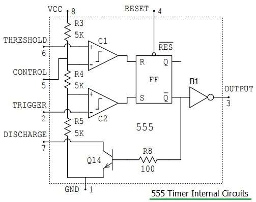
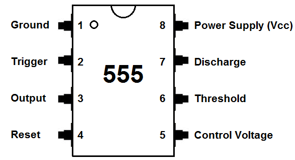
Pinout
We will go over the pinout of the 555 timer. The 555 timer is an 8-pin IC.This means it has 8 different pins, each of which have different functions for the IC.
-
• Pin 1. – Ground, The ground pin connects the 555 timer to the negative (0v) supply rail.
-
• Pin 2. – Trigger, The negative input to comparator No 1. A negative pulse on this pin “sets” the internal Flip-flop when the voltage drops below 1/3Vcc causing the output to switch from a “LOW” to a “HIGH” state.
-
• Pin 3. – Output, The output pin can drive any TTL circuit and is capable of sourcing or sinking up to 200mA of current at an output voltage equal to approximately Vcc – 1.5V so small speakers, LEDs or motors can be connected directly to the output.
-
• Pin 4. – Reset, This pin is used to “reset” the internal Flip-flop controlling the state of the output, pin 3. This is an active-low input and is generally connected to a logic “1” level when not used to prevent any unwanted resetting of the output.
-
• Pin 5. – Control Voltage, This pin controls the timing of the 555 by overriding the 2/3Vcc level of the voltage divider network. By applying a voltage to this pin the width of the output signal can be varied independently of the RC timing network. When not used it is connected to ground via a 10nF capacitor to eliminate any noise.
-
• Pin 6. – Threshold, The positive input to comparator No 2. This pin is used to reset the Flip-flop when the voltage applied to it exceeds 2/3Vcc causing the output to switch from “HIGH” to “LOW” state. This pin connects directly to the RC timing circuit.
-
• Pin 7. – Discharge, The discharge pin is connected directly to the Collector of an internal NPN transistor which is used to “discharge” the timing capacitor to ground when the output at pin 3 switches “LOW”.
-
• Pin 8. – Supply +Vcc, This is the power supply pin and for general purpose TTL 555 timers is between 4.5V and 15V.
Operating Modes
IC555 has three different operating modes. These operating modes actually correspond to three different multivibrator configurations.
-
Astable mode – it is also known as self triggering or free running mode. It has no stable state. It has two quasi stable states that automatically changes from one to another. It changes from high to low state and low to high state without any trigger input after pre determine time. This mode is used to generate square wave oscillations, clock pulse, PWM wave etc.
-
Monostable mode – it is also known as single shot mode. It has one stable state and one quasi stable state. It jumps into quasi stable state from stable state when trigger input is applied and comes back to stable state after pre determine time automatically. It is used in generating pulses, time delay etc.
-
Bistable mode – it is also known as flip-flop mode. It has both stable states. Two different trigger inputs are applied to change the state from high to low and low to high. It is used in automatic switching applications, to generate pulse of variable time etc.
If you want to get more info about this IC, please check this link.
Examples
Test the frequencies of 555 oscillating circuit
Overview
In this example, the Osoyoo Uno board is used to test the frequencies of square waves generated by the 555 oscillating circuit and show them on Serial Monitor.

Connection
Build the circuit as below:
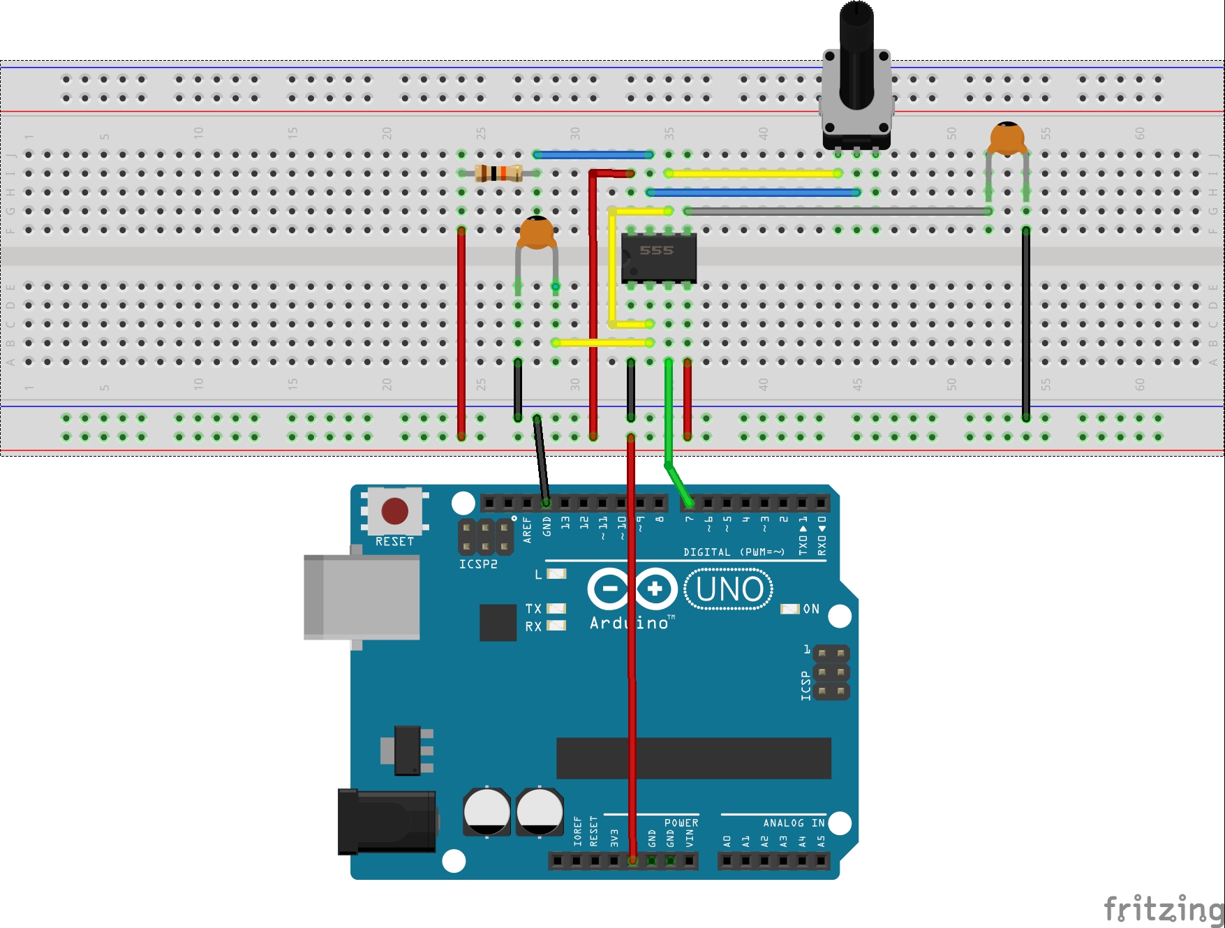
Upload Sketch
After above operations are completed, connect the Arduino board to your computer using the USB cable. The green power LED (labelled PWR) should go on. Load up the following sketch onto your Arduino.
int pin = 7; //pin 7 connected to the third pin of NE555 unsigned long duration; //the variable to store the length of the pulse void setup() { pinMode(pin, INPUT); //set the pin as an input Serial.begin(9600); // start serial port at 9600 bps } void loop() { duration = pulseIn(pin, HIGH); //Reads a pulse on pin Serial.print(duration); //print the length of the pulse on the serial monitor Serial.println(); //print an blank on serial monitor delay(500); //wait for 500 ms }
Running Result
A few seconds after the upload finishes, open the serial monitor,you can see that if you rotate the potentiometer:
The length of the pulse (in microsecond) displayed will change accordingly.


part list is not the one relevant for this 555 example, where can I get the correct part list?
which learning kit you purchased? Can you show us the purchase link?
I purchased Adevanced Starter Kit for Arduino V2.
What is the function of the capacitors in this project, please?
capacitor is recommend by Timer module. If you don’t have capacitor, it should be ok. but Timer might not accurate.