Note: ALL OSOYOO Products for Arduino are Third Party Board which is fully compatitable with Arduino
Authorized Online Retailers:
Content
- Introduction
- Preparations
- About the 4 Digit 7 Segment LED Display
- Examples
Introduction
A Seven-segment display (SSD), or seven-segment indicator, is a form of electronic display device for displaying decimal numerals that is an alternative to the more complex dot matrix displays. Seven-segment displays are widely used in digital clocks, electronic meters, basic calculators, and other electronic devices that display numerical information.
In this lesson, we will be showing you how a 4 digit 7 segment display works and how to use a 4 digit 7 segment display with OSOYOO Basic board. Overhere, we are using the common cathode 4 digit 7 segment display.
Preparations
Hardware
- Osoyoo Basic Board (Fully compatible with Arduino UNO rev.3) x 1
- 4 Digit 7 Segment LED Display x 1
- 74HC595 x 1
- 200 ohm Resistor x 8
- Jumpers
- USB Cable x 1
- PC x 1
Software
- Arduino IDE (version 1.6.4+)
- Arduino Library: TimerOne.h
About 4 Digit 7 Segment LED Display
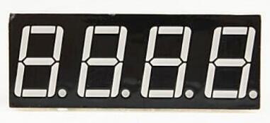
Either a compact module containing four 7- segment LED displays can be used or four individual 7 – segment displays can be used by multiplexing them.
Features
- RoHS Compliance
- Perfect display uniformity for LED segment display
- Low power dissipation
- Wide viewing angle
- Luminous intensity compatible
- Custom design available to individual requirements
Now we are going to see how to interface 4 digit 7 segment display with OSOYOO Basic board. We are going to use a different method to control this Four digit display. Let’s see the pinout of this 4 digit 7 segment display.
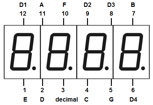
Pin Out – 4 Digit 7 Segment Display
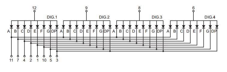
A 4-digit 7-segment LED display has 12 pins. 8 of the pins are for the 8 LEDs on each of the 7 segment displays, which includes A-G and DP (decimal point). The other 4 pins represent each of the 4 digits from D1-D4.
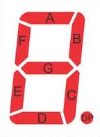

Common Anode or Common Cathode
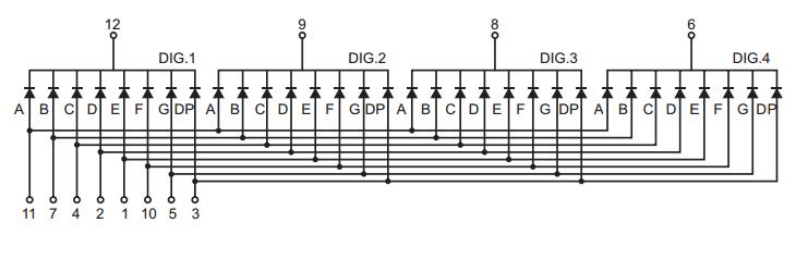
Each segment in the display module is multiplexed, meaning it shares the same anode connection points. And each of the four digits in the module have their own common cathode connection point. This allows each digit to be turned on or off independently. Also, this multiplexing technique turns the massive amount of microcontroller pins necessary to control a display into just eleven or twelve (in place of thirty-two)!
Common Anode
Common Cathode
Multiplexing Technique
So how we are going to display a number like 1234 on this 4 digit display? For this we are going to use a method called multiplexing. What multiplexing does is simple – show one digit at a time on a display unit and switch between display units very fast. Due to persistence of vision, human eye can not differentiate between which display is ON/OFF. The human eye just visualizes all the 4 display units to be ON all the time. Let’s say we need to show 1234. First we turn on the segments relevant to “1” and turn on the 1st display unit. Then we send signals to show “2”, turn off 1st display unit and turn on 2nd display unit. We repeat this process for next two numbers and switching between display units should be done very fast (about within one second delay). As our eyes can’t pick a change occurring repeatedly to any object within 1 second, what we see is 1234 appearing on the display at the same time.
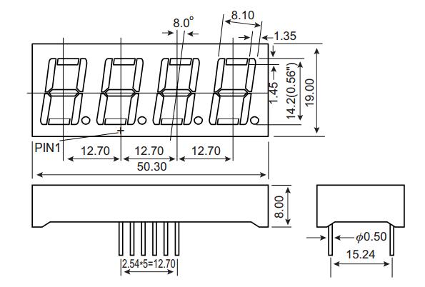
Dimension
Examples
Stop Watch
In this example we will use a 4-digit 7-segment display to make a stopwatch, you can see the number increases by one per second on the 4-digit 7-segment display.
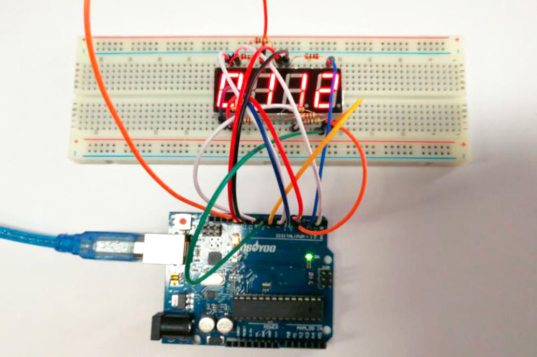
Connection
Build the circuit as below:
The wiring between the 4-digit 7-segment display and the Osoyoo Basic board is as shown below:
|
4-Digit 7-Segment Display
|
Osoyoo Basic board
|
|
a
|
2
|
|
b
|
3
|
|
c
|
4
|
|
d
|
5
|
|
e
|
6
|
|
f
|
7
|
|
g
|
8
|
|
p
|
9
|
|
D1
|
13
|
|
D2
|
12
|
|
D3
|
11
|
|
D4
|
10
|
Code Program
After above operations are completed, connect the board to your computer using the USB cable. The green power LED (labelled PWR) should go on.Open the Arduin IDE and choose corresponding board type and port type for you project. Then load up the following sketch onto your board.
Before you upload the code to your board, make sure you have installed the Arduin library – TimerOne.h.
#include <TimerOne.h>
//the pins of 4-digit 7-segment display attach to pin2-13 respectively
int a = 7;
int b = 3;
int c = 4;
int d = 5;
int e = 6;
int f = 2;
int g = 8;
int p = 9;
int d4 = 10;
int d3 = 11;
int d2 = 12;
int d1 = 13;
long n = 0;// n represents the value displayed on the LED display. For example, when n=0, 0000 is displayed. The maximum value is 9999.
int x = 100;
int del = 5;//Set del as 5; the value is the degree of fine tuning for the clock
int count = 0;//Set count=0. Here count is a count value that increases by 1 every 0.1 second, which means 1 second is counted when the value is 10
void setup()
{
  //set all the pins of the LED display as output
  pinMode(d1, OUTPUT);
  pinMode(d2, OUTPUT);
  pinMode(d3, OUTPUT);
  pinMode(d4, OUTPUT);
  pinMode(a, OUTPUT);
  pinMode(b, OUTPUT);
  pinMode(c, OUTPUT);
  pinMode(d, OUTPUT);
  pinMode(e, OUTPUT);
  pinMode(f, OUTPUT);
  pinMode(g, OUTPUT);
  pinMode(p, OUTPUT);

  Timer1.initialize(100000); // set a timer of length 100000 microseconds (or 0.1 sec - or 10Hz => the led will blink 5 times, 5 cycles of on-and-off, per second)
  Timer1.attachInterrupt( add ); // attach the service routine here
}
/***************************************/
void loop()
{
  clearLEDs();//clear the 7-segment display screen
  pickDigit(0);//Light up 7-segment display d1
  pickNumber((n/1000));// get the value of thousand
  delay(del);//delay 5ms

  clearLEDs();//clear the 7-segment display screen
  pickDigit(1);//Light up 7-segment display d2
  pickNumber((n%1000)/100);// get the value of hundred
  delay(del);//delay 5ms

  clearLEDs();//clear the 7-segment display screen
  pickDigit(2);//Light up 7-segment display d3
  pickNumber(n%100/10);//get the value of ten
  delay(del);//delay 5ms

  clearLEDs();//clear the 7-segment display screen
  pickDigit(3);//Light up 7-segment display d4
  pickNumber(n%10);//Get the value of single digit
  delay(del);//delay 5ms
}
/**************************************/
void pickDigit(int x) //light up a 7-segment display
{
  //The 7-segment LED display is a common-cathode one. So also use digitalWrite to  set d1 as high and the LED will go out
  digitalWrite(d1, HIGH);
  digitalWrite(d2, HIGH);
  digitalWrite(d3, HIGH);
  digitalWrite(d4, HIGH);

  switch(x)
  {
    case 0:
    digitalWrite(d1, LOW);//Light d1 up
    break;
    case 1:
    digitalWrite(d2, LOW); //Light d2 up
    break;
    case 2:
    digitalWrite(d3, LOW); //Light d3 up
    break;
    default:
    digitalWrite(d4, LOW); //Light d4 up
    break;
  }
}
//The function is to control the 7-segment LED display to display numbers. Here x is the number to be displayed. It is an integer from 0 to 9
void pickNumber(int x)
{
  switch(x)
  {
    default:
    zero();
    break;
    case 1:
    one();
    break;
    case 2:
    two();
    break;
    case 3:
    three();
    break;
    case 4:
    four();
    break;
    case 5:
    five();
    break;
    case 6:
    six();
    break;
    case 7:
    seven();
    break;
    case 8:
    eight();
    break;
    case 9:
    nine();
    break;
  }
}
void clearLEDs() //clear the 7-segment display screen
{
  digitalWrite(a, LOW);
  digitalWrite(b, LOW);
  digitalWrite(c, LOW);
  digitalWrite(d, LOW);
  digitalWrite(e, LOW);
  digitalWrite(f, LOW);
  digitalWrite(g, LOW);
  digitalWrite(p, LOW);
}

void zero() //the 7-segment led display 0
{
  digitalWrite(a, HIGH);
  digitalWrite(b, HIGH);
  digitalWrite(c, HIGH);
  digitalWrite(d, HIGH);
  digitalWrite(e, HIGH);
  digitalWrite(f, HIGH);
  digitalWrite(g, LOW);
}

void one() //the 7-segment led display 1
{
  digitalWrite(a, LOW);
  digitalWrite(b, HIGH);
  digitalWrite(c, HIGH);
  digitalWrite(d, LOW);
  digitalWrite(e, LOW);
  digitalWrite(f, LOW);
  digitalWrite(g, LOW);
}

void two() //the 7-segment led display 2
{
  digitalWrite(a, HIGH);
  digitalWrite(b, HIGH);
  digitalWrite(c, LOW);
  digitalWrite(d, HIGH);
  digitalWrite(e, HIGH);
  digitalWrite(f, LOW);
  digitalWrite(g, HIGH);
}
void three() //the 7-segment led display 3
{
  digitalWrite(a, HIGH);
  digitalWrite(b, HIGH);
  digitalWrite(c, HIGH);
  digitalWrite(d, HIGH);
  digitalWrite(e, LOW);
  digitalWrite(f, LOW);
  digitalWrite(g, HIGH);
}

void four() //the 7-segment led display 4
{
  digitalWrite(a, LOW);
  digitalWrite(b, HIGH);
  digitalWrite(c, HIGH);
  digitalWrite(d, LOW);
  digitalWrite(e, LOW);
  digitalWrite(f, HIGH);
  digitalWrite(g, HIGH);
}

void five() //the 7-segment led display 5
{
  digitalWrite(a, HIGH);
  digitalWrite(b, LOW);
  digitalWrite(c, HIGH);
  digitalWrite(d, HIGH);
  digitalWrite(e, LOW);
  digitalWrite(f, HIGH);
  digitalWrite(g, HIGH);
}

void six() //the 7-segment led display 6
{
  digitalWrite(a, HIGH);
  digitalWrite(b, LOW);
  digitalWrite(c, HIGH);
  digitalWrite(d, HIGH);
  digitalWrite(e, HIGH);
  digitalWrite(f, HIGH);
  digitalWrite(g, HIGH);
}

void seven() //the 7-segment led display 7
{
  digitalWrite(a, HIGH);
  digitalWrite(b, HIGH);
  digitalWrite(c, HIGH);
  digitalWrite(d, LOW);
  digitalWrite(e, LOW);
  digitalWrite(f, LOW);
  digitalWrite(g, LOW);
}

void eight() //the 7-segment led display 8
{
  digitalWrite(a, HIGH);
  digitalWrite(b, HIGH);
  digitalWrite(c, HIGH);
  digitalWrite(d, HIGH);
  digitalWrite(e, HIGH);
  digitalWrite(f, HIGH);
  digitalWrite(g, HIGH);
}

void nine() //the 7-segment led display 9
{
  digitalWrite(a, HIGH);
  digitalWrite(b, HIGH);
  digitalWrite(c, HIGH);
  digitalWrite(d, HIGH);
  digitalWrite(e, LOW);
  digitalWrite(f, HIGH);
  digitalWrite(g, HIGH);
}
/*******************************************/
void add()
{
  // Toggle LED
  count ++;
  if(count == 10)
  {
    count = 0;
    n++;
    if(n == 10000)
    {
      n = 0;
    }
  }
}
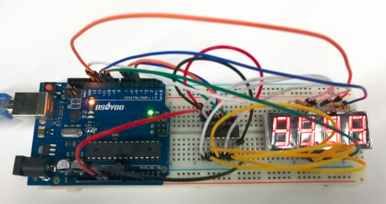
Running Result
A few seconds after the upload finishes, you can see the number increases by one per second on the 4-digit 7-segment display. You can see it as below:
Interfacing 4 Digit 7 Segment Display using Shift Register 74HC595
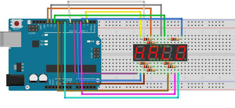
As you can see in the diagram we are using an IC named 74HC595 in addition to OSOYOO Basic board and 4 digit seven segment display. 74HC595 – is a shift register IC and it converts serial data to parallel data. This shift register IC is used to reduce the number of digital I/O pins of Arduino required to control the 7 segment display. As obvious from the circuit diagram, we need only 3 digital pins for Arduino (connected to shift register IC) to control 8 segment lines of 4 digit seven segment display.
Connection
Build the circuit as below:
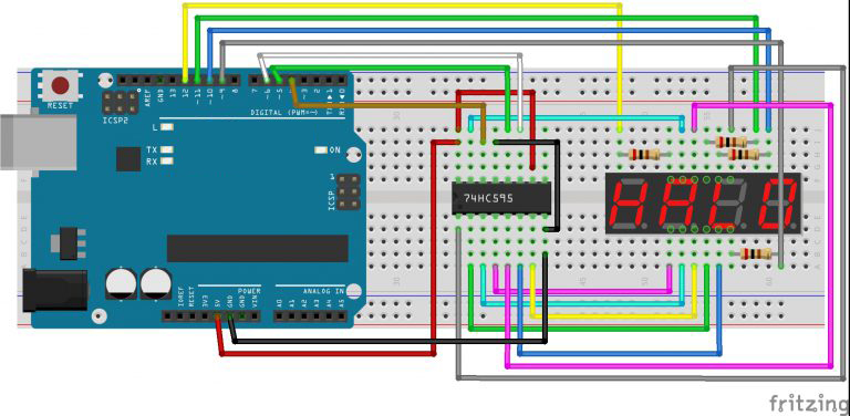
All the segments of 7 segment display are connected to the parallel data output pins of the shift register. Clock, latch and serial data pins of the shift register are connected to digital pins 6,5 & 4 respectively. Each of the four common anode pins are connected to a unique pin (9,10,11 and 12) through a 200Ω resistor to limit the current.
Code Program
After above operations are completed, connect the board to your computer using the USB cable. The green power LED (labelled PWR) should go on.Open the Arduin IDE and choose corresponding board type and port type for you project. Then load up the following code onto your board.
You need to install the timer library before you compile this code. Download the library and install it into your arduin library.
#include "Timer.h" //include timer library
Timer t; // craete a timer object
long number = 0; //declear the variables
int first_digit = 0;
int second_digit = 0;
int third_digit = 0;
int fourth_digit = 0;
int timer_event = 0;
int CA_1 = 12;
int CA_2 = 11;
int CA_3 = 10;
int CA_4 = 9;
int clk = 6;
int latch = 5;
int data = 4;
int count = 0;
int digits[4] ;
int CAS[4] = {12, 11, 10, 9};
byte numbers[10] {B11111100, B01100000, B11011010, B11110010, B01100110, B10110110, B10111110, B11100000, B11111110, B11110110};
//byte combinations for each number 0-9
void setup() {
  Serial.begin(9600); //serial start and pin config
  pinMode(CA_1, OUTPUT);
  pinMode(CA_2, OUTPUT);
  pinMode(CA_3, OUTPUT);
  pinMode(CA_4, OUTPUT);
  pinMode(clk, OUTPUT);
  pinMode(latch, OUTPUT);
  pinMode(data, OUTPUT);
  digitalWrite(CA_1, HIGH);
  digitalWrite(CA_2, HIGH);
  digitalWrite(CA_3, HIGH);
  digitalWrite(CA_4, HIGH);
  Serial.println("please Enter a number from 0 to 9999");
}

void loop() {
  t.update(); //timer update
  if (Serial.available()) { // read from serial
    t.stop(timer_event); //stop timer if anythign to read
    cathode_high(); // blank the screen
    String s = Serial.readString(); //read the serail value
    number = (long)s.toInt(); //convert it to int
    if (number > 9999) { //check the number is 0-9999
      Serial.println("Please Enter Number Between 0 - 9999");
    } else {
      break_number(number);
      timer_event = t.every(1, display_number); // start timer again
    }
  }
}

void break_number(long num) { // seperate the input number into 4 single digits

  first_digit = num / 1000;
  digits[0] = first_digit;

  int first_left = num - (first_digit * 1000);
  second_digit = first_left / 100;
  digits[1] = second_digit;
  int second_left = first_left - (second_digit * 100);
  third_digit = second_left / 10;
  digits[2] = third_digit;
  fourth_digit = second_left - (third_digit * 10);
  digits[3] = fourth_digit;
}

void display_number() { //scanning

  cathode_high(); //black screen
  digitalWrite(latch, LOW); //put the shift register to read
  shiftOut(data, clk, LSBFIRST, numbers[digits[count]]); //send the data
  digitalWrite(CAS[count], LOW); //turn on the relevent digit
  digitalWrite(latch, HIGH); //put the shift register to write mode
  count++; //count up the digit
  if (count == 4) { // keep the count between 0-3
    count = 0;
  }
}

void cathode_high() { //turn off all 4 digits
  digitalWrite(CA_1, HIGH);
  digitalWrite(CA_2, HIGH);
  digitalWrite(CA_3, HIGH);
  digitalWrite(CA_4, HIGH);
}
Important code lines are commented in the code. In this code you can send any number from 0 – 9999 through the serial monitor (refer the image given above). We are using the arduin timer interrupts to switch between digits. The segments should be turn on and off for each number is stored in a byte array. In the loop() – serial values are read and converted to int and then to long data types. Then this long data is broke in to single digits by break_number () method. Multiplexing is done by the timer class every() function and it calls display_number() method once every millisecond. This method use arduin shiftOut () function to send signals to shift register. Note how latch pin is turned LOW before we send data and turned HIGH after sending data. The function called cathode_high() is to turn off the screen.
Running Result
A few seconds after the upload finishes, open the Serial Monitor and you will see:
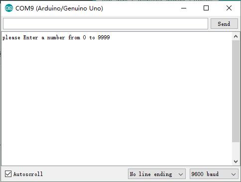
The number we input in the serial monitor will be displayed on the 4 digit 7 segment display, we enter the following numbers in turn: 1, 66, 123, 1234, 9999, you can see the result as below:


Hi
I need to display time in seconds and milliseconds. Example 13.52 sec
Maximum time 99 seconds.
What changes to be made in the code?