Note: ALL OSOYOO Products for Arduino are Third Party Board which is fully compatitable with Arduino
Authorized Online Retailers:
Content
- Introduction
- Preparations
- About Potentiometer
- Connection
- Upload Sketch
- Program Running Result
- The Expansion Example
Introduction
In this lesson, we will use a potentiometer attached to analog pin A0 and an LED attached to digital pin 9. We use the input from the analog pin to adjust the timing delay of a blinking LED.
Preparations
Hardware
- Osoyoo Basic Board (Fully compatible with Arduino UNO rev.3) x 1
- Breadboard x 1
- Potentiometer(10k) x 1
- 200 ohm resistor x 1
- LED x 1
- M/M jumpers
- USB Cable x 1
- PC x 1
Software
Arduino IDE (version 1.6.4+)
About Potentiometer

A potentiometer is a simple knob that provides a variable resistance, which we can read into the OSOYOO Basic board as an analog value.In this example, that value controls the rate at which an LED blinks.
So what’s the difference between an analog value and a digital one? Simply put, digital means on/off, high/low level with just two states, i.e. either 0 or 1. But the data state of analog signals is linear, for example, from 1 to 1000; the signal value changes over time instead of indicating an exact number. Analog signals include those of light intensity, humidity, temperature, and so on.
In this lesson, a potentiometer, or pot, is used to change the current in the circuit so the blink rate of the LED will change accordingly. And since the pot is an analog device, the current change is smooth, thus the blink rate will gradually get faster or slower instead of going through an obvious stepwise process.
What we mean by PWM here is the digitalization of analog signals, which is a process of approaching analog signals. Since the potentiometer inputs analog signals, it should be connected to analog ports, i.e. A0-A5, instead of digital ports.
| Electronic symbol |
 (International) (International)
 (US/Canada) (US/Canada) |
Connection
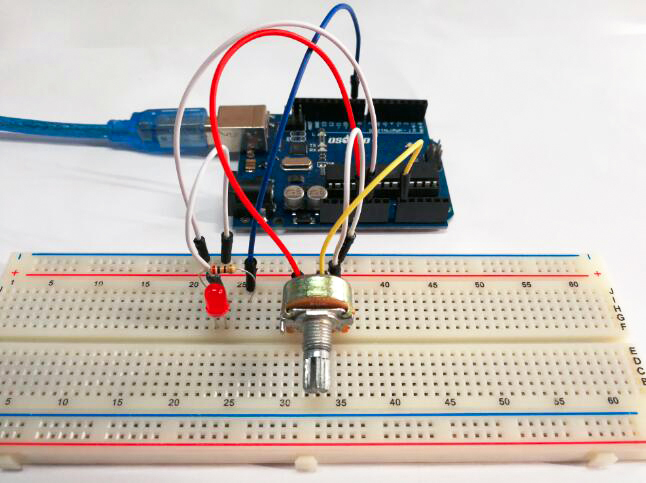
Build the circuit as below:
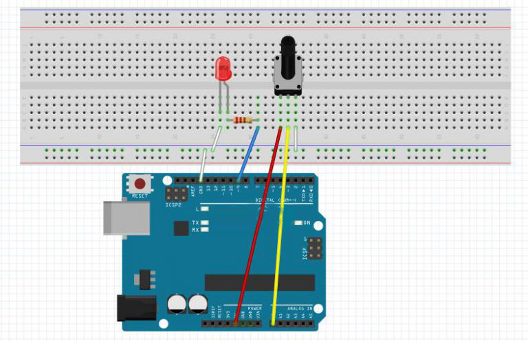
We connect three wires to the board. The first goes to ground from one of the outer pins of the potentiometer. The second goes from 5 volts to the other outer pin of the potentiometer. The third goes from analog input 0 to the middle pin of the potentiometer.
Upload Sketch
After above operations are completed, connect the board to your computer using the USB cable. The green power LED (labelled PWR) should go on.
Code Program
You can download the sketch from this link or copy below code to your Arduin IDE window:
int potPin = A0;    // select the input pin for the potentiometer
int ledPin = 9;   // select the pin for the LED
int val = 0;       // variable to store the value coming from the sensor

void setup() {
  pinMode(ledPin, OUTPUT);  // declare the ledPin as an OUTPUT
}

void loop() {
  val = analogRead(potPin);    // read the value from the sensor
  digitalWrite(ledPin, HIGH);  // turn the ledPin on
  delay(val);                  // stop the program for some time
  digitalWrite(ledPin, LOW);   // turn the ledPin off
  delay(val);                  // stop the program for some time
}
By turning the shaft of the potentiometer, we change the amount of resistence on either side of the wiper which is connected to the center pin of the potentiometer. This changes the relative “closeness” of that pin to 5 volts and ground, giving us a different analog input. When the shaft is turned all the way in one direction, there are 0 volts going to the pin, and we read 0. When the shaft is turned all the way in the other direction, there are 5 volts going to the pin and we read 1023. In between, analogRead() returns a number between 0 and 1023 that is proportional to the amount of voltage being applied to the pin.
Compile and upload
Open the Arduin IDE and select corresponding board type and port type for your board.
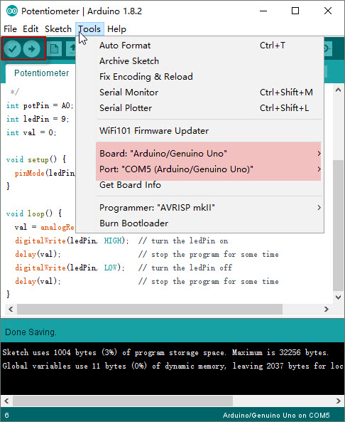
After compile this sketch, simply click the “Upload” button in the environment. Wait a few seconds – you should see the RX and TX leds on the board flashing. If the upload is successful, the message “Done uploading.” will appear in the status bar.
Running Result
A few seconds after the upload finishes, adjust the knob of the potentiometer to adjust the timing delay of a blinking LED:
Extended experiment
In the previous course, you have learned how to control an LED by PWM programming, which is interesting though sounds slightly abstract. In this part, you will learn how to change the luminance of an LED by potentiometer.
The circuit of this part is same as above.You can get the sketch from this link or copy below code to your new Arduin IDE window and upload it to your board. Don’t forget to choose the corresponding board and port for you project!
const int analogPin = A0;//the analog input pin attach to
const int ledPin = 9;//the led attach to
int inputValue = 0;//variable to store the value coming from sensor
int outputValue = 0;//variable to store the output value

void setup()
{
}

void loop()
{
inputValue = analogRead(analogPin);//read the value from the sensor
outputValue = map(inputValue,0,1023,0,255);//Convert from 0-1023 proportional to the number of a number of from 0 to 255
analogWrite(ledPin,outputValue);//turn the led on depend on the output value
}
As you see, the potentiometer is connected to pin A0 of the Osoyoo Basic board, which can measure voltages from 0V to 5V. The corresponding returned value is from 0 to 1024. The measurement accuracy for voltage change is relatively high.
A few seconds after the upload finishes,rotate the shaft of the potentiometer and you should see the luminance of the LED change.:


