Objective:
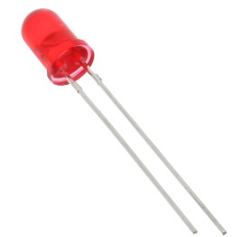
In this project, we will read tilt sensor signal from GPIO port 20 (Pin 38) and control the status of LED. When Pin 38 get high voltage(True), we turn on LED , otherwise turn off LED. The input signal value(1 or 0) will be displayed to screen every 0.1 second.
1)Raspbian should be upgraded to latest version in order to support RPI.GPIO module
Please run following commands in shell:
sudo apt-get update
sudo apt-get upgrade
2)Enable I2C and SPI protocol
To enable the protocol, run shell command
sudo raspi-config
Then select Advance Options and enable I2C and SPI
You need to reboot to effect the configuration
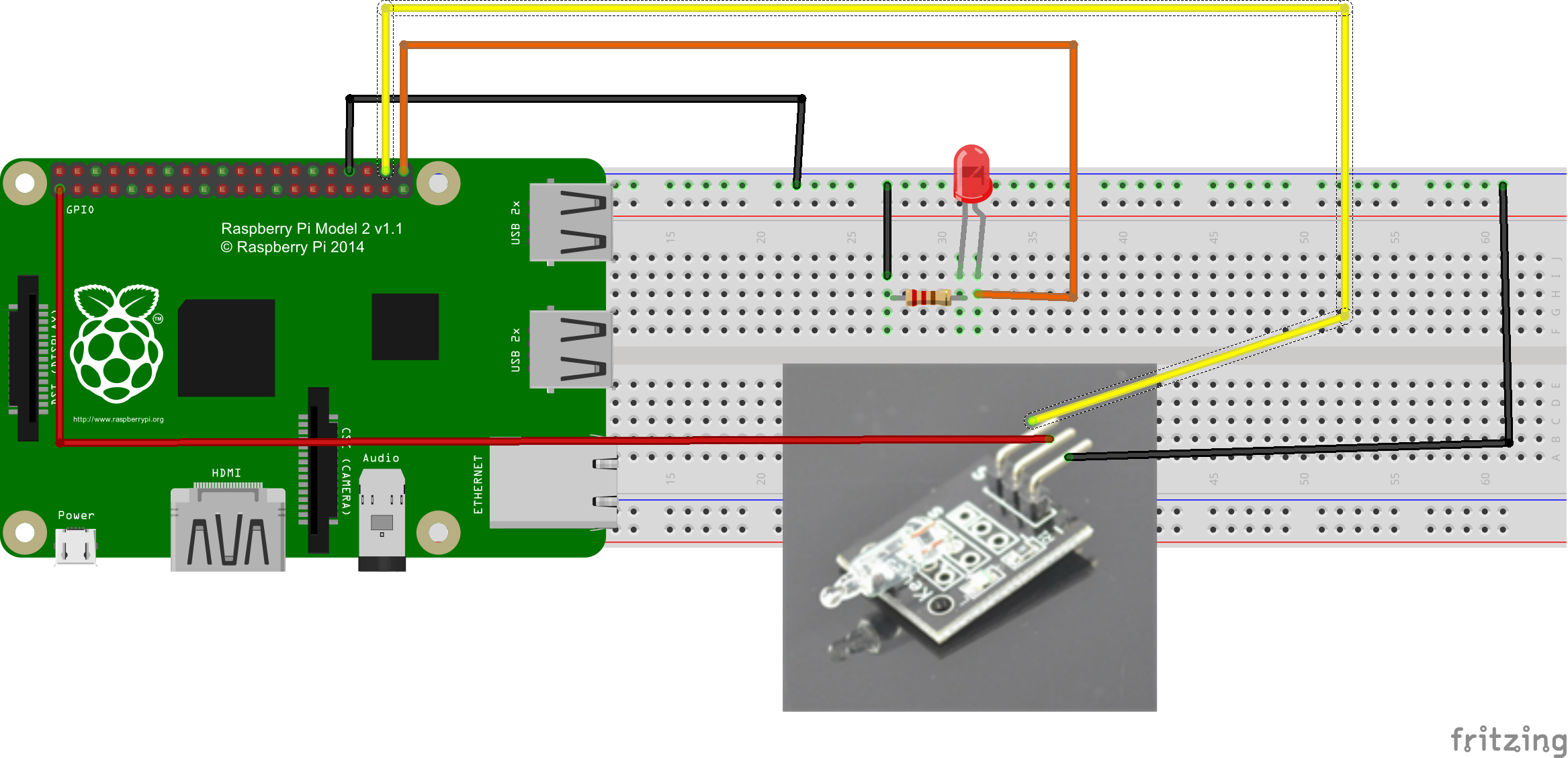
Connect circuit components as per following graph:
Caution: Unlike Arduino board 5V input voltage, Raspberry GPIO pin accept only 3 Volt. Wrong voltage input might damage the Pi board. Please be very careful!
Write python code
You have two way to write python code:
Option 1)
Run following command in shell window:
sudo nano gpiosensor.py
then copy python code and paste the code into gpiosensor.py
Then Type Ctrl X and Yes to save the file. and press enter
Option 2)https://osoyoo.com/wp-admin/post.php?post=804&action=edit#
You can also download above python file from our server by typing following shell command:
sudo wget http://osoyoo.com/driver/gpiosensor.py
Finally, run following command in shell window:
sudo python gpiosensor.py
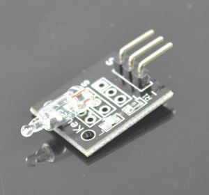
If you turn the sensor board into vertical position, the pi will turn on LED. If you put the board into horizon position, the LED will be off.
I just got a pi 3 b and I have the one from amozon it is preloaded with noobs I beleave is the programing site radpbain on this ? New and have no clue please help!


I just got a pi 3 b and I have the one from amozon it is preloaded with noobs I beleave is the programing site radpbain on this ? New and have no clue please help!
you need to install raspbain, Noobs is the bootstrap not an OS.
After you install raspbain, the raspberry pi need to connect with Internet.
回路図の水銀チルトセンサーの配線に注意。
回路図の赤線はVCC、黒線はGND、黄線にDOを接続する必要がある。
ところで、水銀チルトセンサー上の+は何でしょうか?
回すとどうなりますか?部品の仕様が知りたいです。
お問い合わせ、ありがとうございます。
水銀チルトセンサー上の+はVCC、-はGND、SはD0(信号出力)の意味です。
どうぞよろしくお願い致します。