Note: ALL OSOYOO Products for Arduino are Third Party Board which is fully compatitable with Arduino
Authorized Online Retailers:
Content
- Introduction
- Preparations
- Connection
- Upload Sketch
- Code Analysis
- Connecting, Receiving and Sending Data to the board
Introduction
In this lesson, I will be going through on how to setup the serial monitor so you can debug and interact with a program running on the board. This is pretty simple but it can be a bit confusing at first especially if you’re new to programing and the board.
As part of this lesson we will build a simple circuit to demonstrate how you can both receive and send commands over the serial monitor.
Preparations
Hardware
- Osoyoo basic Boars (Fully compatible with Arduino UNO rev.3) x 1
- Breadboard x 1
- 200 ohm resistor x 1
- LED x 1
- M/M jumpers
- USB Cable x 1
- PC x 1
Software
IDE (version 1.6.4+)
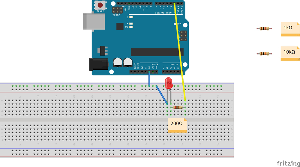
Connection
You connect the components as shown in the diagram below.
Upload Sketch
After above operations are completed, connect the board to your computer using the USB cable. The green power LED (labelled PWR) should go on.
Code Program
You can download the sketch from this link or copy below code to your IDE window:
int redLedPin = 2; // Pin Red LED is connected to
int count = 0;
void setup() {
pinMode(redLedPin, OUTPUT); //Set led pin to output
Serial.begin(9600); //Set serial to the 9600 band
while (! Serial); // Allow serial to initialise
Serial.println("Enter Y to turn on the LED:");
}
void loop() {
if (Serial.available())  {
char ch = Serial.read();
if (ch == 'y'||ch == 'Y')
{
digitalWrite(redLedPin, HIGH);
Serial.println("You have turned on the LED!!");
Serial.print("The LED was off for ");
Serial.print(count);
Serial.println(" seconds");
Serial.println("If you want to switch it off, simply enter N or n!");
count = 0;
}
if (ch == 'n'||ch == 'N')  {
digitalWrite(redLedPin, LOW);
Serial.println("You have turned off the LED!!");
Serial.print("The LED was on for ");
Serial.print(count);
Serial.println(" seconds");
Serial.println("If you want to switch it on, simply enter Y or y!");
count = 0;
}
}
delay(1000);  count += 1;
}
Compile and upload
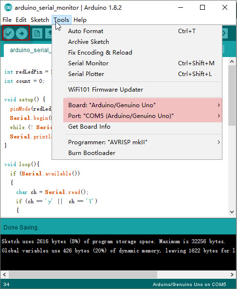
Open the IDE and select corresponding board type and port type for your board.
After compile this sketch, simply click the “Upload” button in the environment. Wait a few seconds – you should see the RX and TX leds on the board flashing. If the upload is successful, the message “Done uploading.” will appear in the status bar.
A few seconds after the upload finishes, click on the right-most button on the toolbar in the IDE. The button is circled below.

The following window will open.
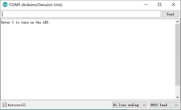
This window is called the Serial Monitor and it is part of the IDE software. Its job is to allow you to both send messages from your computer to an board (over USB) and also to receive messages from the board.
Code Analysis
The code we will be using is again very simple with its purpose is to show the basics of how you can use the Serial monitor to view and send data. I will explain each of the lines we’re using and how you can use it in your next project to debug or interact with the board. If you just want to download the code straight away then you can download it form here.
To begin we initialise an integer variable for our LED, this is the pin number leading to the LED. We also initialize a variable called count, this will store the amount of time the LED is on or off.
int redLedPin = 2;
int count = 0;
In the setup function we first set the red LED to act as an output so we can turn it off and on.
We then call theserial.beginfunction with a parameter value of 9600. The value we’re setting is known as the bits per second (baud) rate. This can be set to quite a few different rates but we will use 9600 as this seems to be the default and will work with most devices without any issues. It is very important to call this otherwise you won’t be able to communicate with the board.
Next we wait for the serial interface to initialise and connect to the computer/device. We then call a function calledSerial.println().This function allows us to print a line to the serial monitor. You will notice this will print the text and then start on a new line for the next input/output.
void setup() {
  pinMode(redLedPin, OUTPUT);
  Serial.begin(9600);
  while (! Serial);
  Serial.println("Enter Y to turn on the LED:");
}
Lastly we have the loop, this will continually loop through until either a new program is uploaded or the board is switched off.
Inside the loop function we have an if statement checking to see if there is data waiting in the serial buffer(Serial.Available). In simple terms we’re checking to see if we have sent a command to it. If there is data, we enter the if statement.
Next we create a variable calledchand callSerial.read()which will get us the data currently waiting in the serial buffer. Keep in mind this function will only get us the first byte of the data that is incoming to the board. If you want to get an entire string you will need to use something likeSerial.readString.
If the byte of data is either y or n we then enter the relevant if statement. In here you will notice we change the output of the LED pin high or low. We then print out a series of statements. There are two things you should notice here.Serial.printlnwill print the data and go to a new line whilstSerial.printwill print the data but stay on the same line when outputting. You will also notice you can print variables such as thecountexample in the code below. Doing this will allow you to be able to debug values when it comes to data processing.
Lastly I delay by a second and add 1 to count. This is just showing you an example of adding data to a variable then printing it via the serial output.
void loop(){
  if (Serial.available()){
    char ch = Serial.read();
    if (ch == 'y' ||	ch == 'Y'){
      digitalWrite(redLedPin, HIGH);
      Serial.println("You have turned on the LED!!");
      Serial.print("The LED was off for ");
      Serial.print(count);
      Serial.println(" seconds");
      Serial.println("If you want to switch it off, simply enter N or n!");
      count = 0;
    }
    if (ch == 'n' ||	ch == 'N'){
      digitalWrite(redLedPin, LOW);
      Serial.println("You have turned off the LED!!");
      Serial.print("The LED was on for ");
      Serial.print(count);
      Serial.println(" seconds");
      Serial.println("If you want to switch it on, simply enter Y or y!");
      count = 0;
    }
  }
    delay(1000);
    count += 1;
}
Once you’re done you should be able to deploy the code onto the board. In the next part I will show you how to connect, receive and send data to the board.
Connecting, Receiving and Sending Data to the board
Now that the code has been uploaded to the board we will need to open up the serial monitor. This is pretty easy and there are only a few options that I will need to explain.
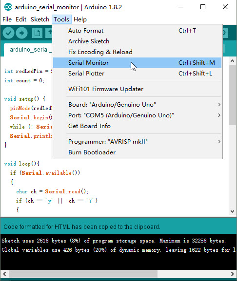
To open up the serial monitor go up to tools and then select the serial monitor. Alternatively, CTRL+SHIFT+M will also bring up the same window. Make sure you are hooked up to the board otherwise the window won’t open up.
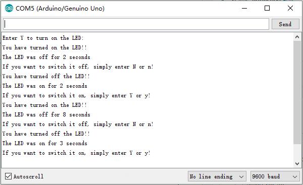
You should now have a window open that looks similar to the one below.
At the top of this screen there should be an input area. This is where you can type and send text to the board. To send the text that you have typed simply press the send button.
Below this is the output window, all the data that is sent to us will be displayed here. If you’re using the example code above you will be able to see the text that is in the Serial.println functions.
At the bottom we have 3 different options. The first is pretty self-explanatory, auto scroll will disable and enable the automatically scrolling of the output box.
Second we have the line ending option. You can set the monitor to automatically append a line ending after what you enter/send to the board.
Thirdly we have the baud rate that I mentioned above. Make sure this matches to what you have set in the code. If it is different than the output text will appear as gibberish. If you’re receiving gibberish, then this is a likely cause of this.
This is basically everything you need to know to understand the basics of the serial monitor. There are a few more things you can learn about such as using strings via the serial interface and more but this probably all you need to know for now.
I hope you now understand how to use the serial monitor correctly and will help you in future projects for Arduino. If I have missed something, got something wrong , you have feedback or anything else then feel to leave a comment below.


