Introduction
In this lesson, we are going to learn how to control both the direction and speed of a small DC motor using an Arduino and the L293D motor driver chip, so first of all we need to understand what is a DC motor and what is a L293D chip.
Preparations
HARDWARE
- Osoyoo UNO Board (Fully compatible with Arduino UNO rev.3) x 1
- Breadboard x 1
- DC Motor x 1
- L293D Driver chip x 1
- 10k Potentiometer x 1
- Switch Button x 1
- Arduino power supply module x 1
- Button head x 1
- M/M jumpers
- USB Cable x 1
- PC x 1
About the DC Motor
OVERVIEW
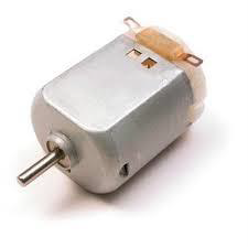
A DC Motor is a type of electric motor that converts DC electrical power to mechanical power i.e. a DC supply is converted to rotation or movement. DC motors are one of the commonly used motors in different applications like electronic toys, power tools, portable fans, etc.
DC Motors are further classified in to different types like series, shunt and compound and each type is used in different areas of applications. Some DC motors are also used in Robotic and Industrial applications for their easy control and precision.
Since DC motors are generally associated with small to medium applications, where the system mainly consists of a Microcontroller as the main processing unit, controlling and driving a DC motor is very important. This is because, driving a motor directly using the microcontroller is not advised (sometimes not possible) as the current from the Microcontroller is very small (usually less than 30mA). Before you connect the circuit, check this link for how to power the dc motor correctly, thanks for the www.sharetechnote.com!
The DC motor (Direct Current motor) is the most common type of motor. DC motors normally have just two leads, one positive and one negative. If you connect these two leads directly to a battery, the motor will rotate. If you switch the leads, the motor will rotate in the opposite direction.
FEATURES
- Operating Temperature: -10°C ~ +60°C
- Rated Voltage: 6.0VDC
- Rated Load: 10 g*cm
- No-load Current: 70 mA max
- No-load Speed: 9100 ±1800 rpm
- Loaded Current: 250 mA max
- Loaded Speed: 4500 ±1500 rpm
- Starting Torque: 20 g*cm
- Starting Voltage: 2.0
- Stall Current: 500mA max
- Body Size: 27.5mm x 20mm x 15mm
- Shaft Size: 8mm x 2mm diameter
- Weight: 17.5 grams
About the L293D Driver Chip
Microcontrollers and single board computers cant directly drive motors or inductive loads. A transistor or a MOSFET can be used but what if you want to be able to reverse a motor? That is where the H-bridge comes in!
An H-bridge is an integrated circuit that allows voltage to each output to be applied both ways. Each output can be configured either a positive or a ground in the circuit meaning a motor can be driven in either direction with relative ease.
OVERVIEW
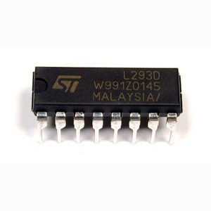
As the name suggests, L293D is a quadruple H-bridge, high current motor driver IC. It can be used to drive two motors at a time in both the directions with an output current of 600mA for each motor. L293D IC is designed to drive relays, DC motors, stepper motors and other inductive loads with high current and high voltage requirements.
SPECIFICATIONS
- Supply Voltage Range 4.5V to 36V
- 600-mA Output current capability per driver
- Separate Input-logic supply
- It can drive small DC-geared motors, bipolar stepper motor.
- Pulsed Current 1.2-A Per Driver
- Thermal Shutdown
- Internal ESD Protection
- High-Noise-Immunity Inputs
PIN DIAGRAM OF L293D
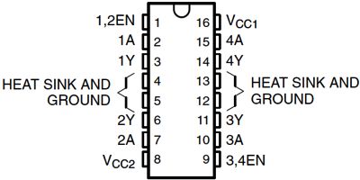
1,2EN: To activate the channel 1 and 2 we supply +5v to this pin.
3,4EN: To activate the channel 3 and 4 we supply +5v to this pin.
Vcc1: Input voltage to derive the internal circuit (darligton array) = 4.5 to 36 v
Vcc2: Supply/Output to appear at output = 4.5 to 36 v
1A: Channel-1 Input Pin
2A: Channel-2 Input Pin
3A: Channel-3 Input Pin
4A: Channel-4 Input Pin
1Y: Channel-1 Output Pin
2Y: Channel-2 Output Pin
3Y: Channel-3 Output Pin
4Y: Channel-4 Output Pin
More info about the L293D chip, please check this link. thanks for the www.microcontroller-project.com!
Examples
DRIVE THE DC MOTOR BY L293D CHIP
In this experiment, we will learn how to control the direction and speed of a small-sized DC motor bya driver chip L293D. Making simple experiments, we will just make the motor rotate left and right,and accelerate or decelerate automatically.
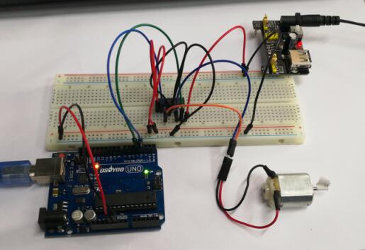
Connection
Connect pin 1A and 2A of the L293D to pin 9 and 10 of the Arduino board, and two pins of the motorto pin 1Y and 2Y of L293D.
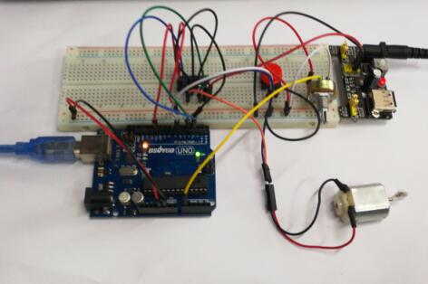
Build the circuit as below:
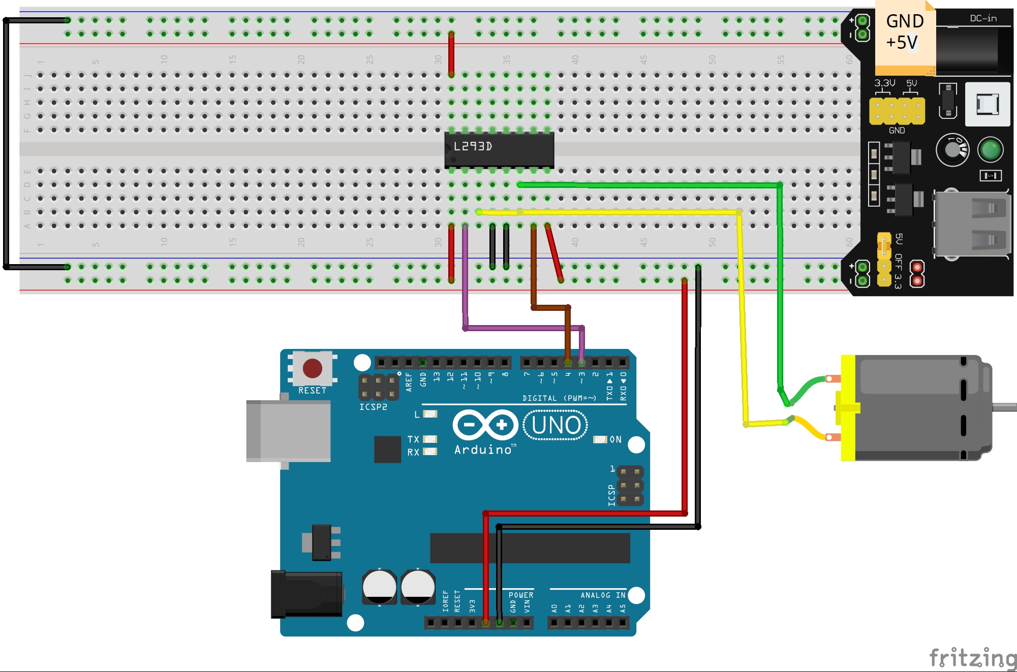
Overhere, you could replace the battery box with the power module
Code Program
After above operations are completed, connect the Arduino board to your computer using the USB cable. The green power LED (labelled PWR) should go on.Open the Graphical Programming software Mixly and follow the next operations:
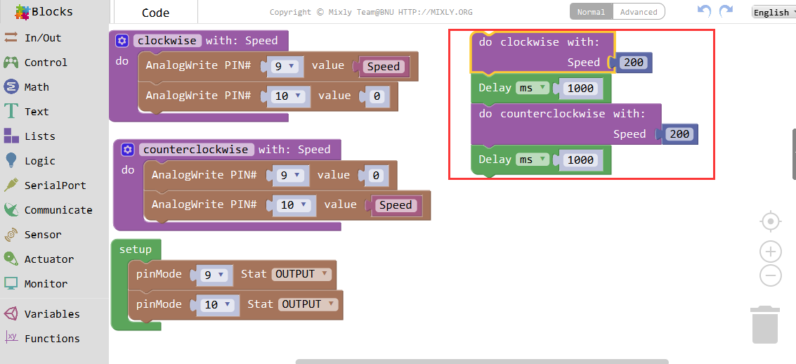
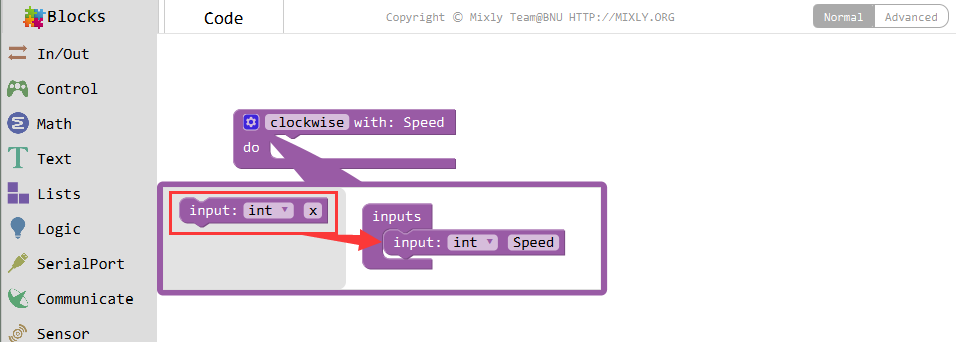
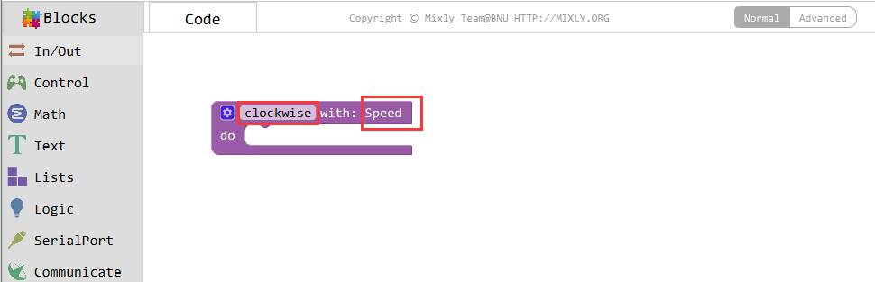
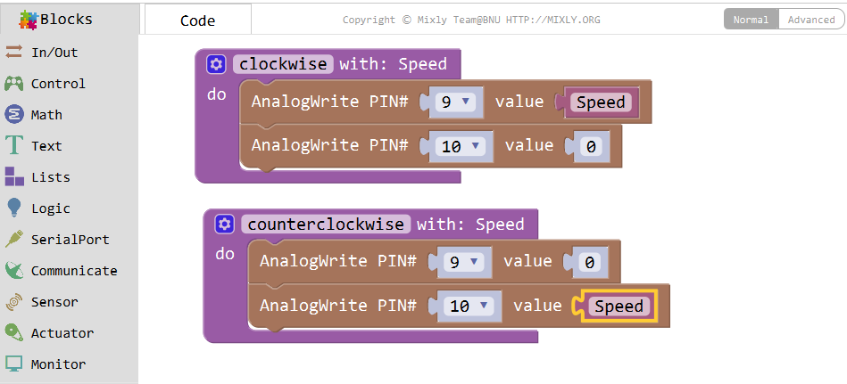
Connect pin 1A and 2A of the L293D to pin 9 and 10 of the Arduino board, and two pins of the motorto pin 1Y and 2Y of L293D. Set a function clockwise for the motor clockwise spinning, and a variableg speed, with the do Procedure block.
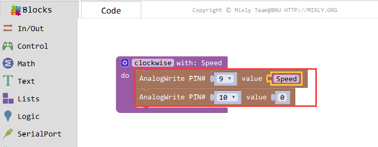
Set pin 9 to high and pin 10 to low with Analogwrite, and the motor will rotate clockwise.
Next, define another function for the motor to spin counterclockwise. Set pin 10 to high and pin 9to low, and then the motor will rotate anticlockwise.
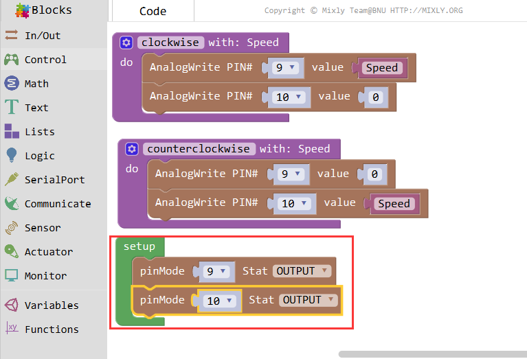
Setup pin 9 and 10 to OUTPUT with pinMode.
Then set the Speed value to 200.

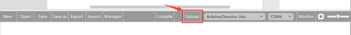
Click Save aftogramming is done. Select the board type and serial port before uploading. For instause a Uno board, just select Arduino/Genuino Uno: if you use a Mega2560, select Arduino/Genuino Mega or Mega2560. 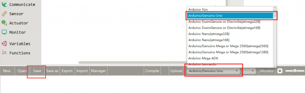
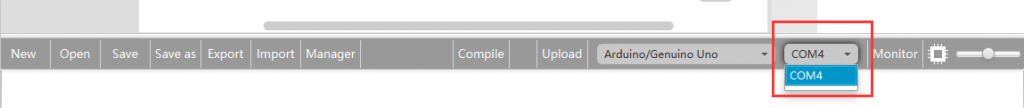
Select the serial device of the Arduino board from the COM menu. This is likely to be COM3 or higher (COM1 and COM2 are usually reserved for hardware serial ports). To find out, you can disconnect your Arduino board and re-open the menu; the entry that disappears should be the Arduino board. Reconnect the board and select that serial port.
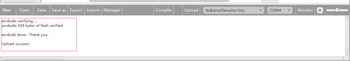
Next,upload the code. If the uploading fails, check and correct the code according to the prompts


Finally, the staus will change to ‘Upload success!’.

Running Result
A few seconds after the upload finishes, the DC motor will start to rotate about, and the speed will change accordingly.