Introduction
The Ultrasonic Sensor sends out a high-frequency sound pulse and then times how long it takes for the echo of the sound to reflect back. The sensor has 2 openings on its front. One opening transmits ultrasonic waves, the other receives them. In this lesson we will show you how the HC-SR04 Ultrasonic Sensor works and how to use it with the Osoyoo Uno board.

Preparations
HARDWARE
- Osoyoo UNO Board (Fully compatible with Arduino UNO rev.3) x 1
- Ultrasonic Sensor HC-SR04 x 1
- I2C LCD1602 x 1
- Breadboard x 1
- Jumpers
- USB Cable x 1
- PC x 1
About Ultrasonic Sensor HC-SR04
FEATURES OF HC-SR04
- Power Supply :+5V DC
- Quiescent Current : <2mA
- Working Currnt: 15mA
- Effectual Angle: <15°
- Ranging Distance : 2cm – 400 cm/1″ – 13ft
- Resolution : 0.3 cm
- Measuring Angle: 30 degree
- Trigger Input Pulse width: 10uS
- Dimension: 45mm x 20mm x 15mm
WHAT IS ULTRASONIC SENSOR ?
An Ultrasonic sensor is a device that can measure the distance to an object by using sound waves. It measures distance by sending out a sound wave at a specific frequency and listening for that sound wave to bounce back. By recording the elapsed time between the sound wave being generated and the sound wave bouncing back, it is possible to calculate the distance between the sonar sensor and the object.
WHAT IS HC-SR04 ?
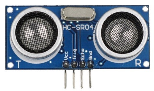
The HC-SR04 ultrasonic sensor uses sonar to determine distance to an object like bats do. It offers excellent non-contact range detection with high accuracy and stable readings in an easy-to-use package. From 2cm to 400 cm or 1” to 13 feet. It operation is not affected by sunlight or black material like Sharp rangefinders are (although acoustically soft materials like cloth can be difficult to detect). It comes complete with ultrasonic transmitter and receiver module.

On the front of the ultrasonic range finder are two metal cylinders. These are transducers. Transducers convert mechanical forces into electrical signals. In the ultrasonic range finder, there is a transmitting transducer and receiving transducer. The transmitting transducer converts an electrical signal into the ultrasonic pulse, and the receiving transducer converts the reflected ultrasonic pulse back into an electrical signal. If you look at the back of the range finder, you will see an IC behind the transmitting transducer labelled MAX3232. This is the IC that controls the transmitting transducer. Behind the receiving transducer is an IC labelled LM324. This is a quad Op-Amp that amplifies the signal generated by the receiving transducer into a signal that’s strong enough to transmit to the Arduino.
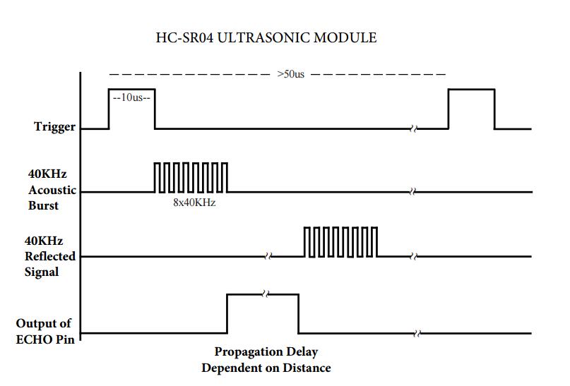
TIMING DIAGRAM
The timing diagram of HC-SR04 is shown. To start measurement, Trig of SR04 must receive a pulse of high (5V) for at least 10us, this will initiate the sensor will transmit out 8 cycle of ultrasonic burst at 40kHz and wait for the reflected ultrasonic burst. When the sensor detected ultrasonic from receiver, it will set the Echo pin to high (5V) and delay for a period (width) which proportion to distance. To obtain the distance, measure the width (Ton) of Echo pin.
Time = Width of Echo pulse, in us (micro second)
- Distance in centimeters = Time / 58
- Distance in inches = Time / 148
Or you can utilize the speed of sound, since it is known that sound travels through air at about 344 m/s (1129 ft/s), you can take the time for the sound wave to return and multiply it by 344 meters (or 1129 feet) to find the total round-trip distance of the sound wave. Round-trip means that the sound wave traveled 2 times the distance to the object before it was detected by the sensor; it includes the ‘trip’ from the sonar sensor to the object AND the ‘trip’ from the object to the Ultrasonic sensor (after the sound wave bounced off the object). To find the distance to the object, simply divide the round-trip distance in half.
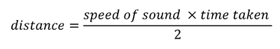
The time variable is the time it takes for the ultrasonic pulse to leave the sensor, bounce off the object, and return to the sensor. We actually divide this time in half since we only need to measure the distance to the object, not the distance to the object and back to the sensor. The speed variable is the speed at which sound travels through air.
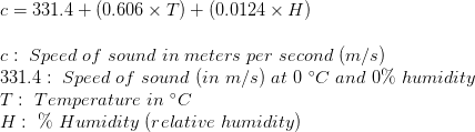
The speed of sound in air changes with temperature and humidity. Therefore, in order to accurately calculate distance, we’ll need to consider the ambient temperature and humidity. The formula for the speed of sound in air with temperature and humidity accounted for is:
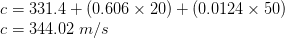
For example, at 20 °C and 50% humidity, sound travels at a speed of:
NOTE
The accuracy of Ultrasonic sensor can be affected by the temperature and humidity of the air it is being used in. However, for these tutorials and almost any project you will be using these sensors in, this change in accuracy will be negligible.
It is important to understand that some objects might not be detected by ultrasonic sensors. This is because some objects are shaped or positioned in such a way that the sound wave bounces off the object, but are deflected away from the Ultrasonic sensor. It is also possible for the object to be too small to reflect enough of the sound wave back to the sensor to be detected. Other objects can absorb the sound wave all together (cloth, carpeting, etc), which means that there is no way for the sensor to detect them accurately. These are important factors to consider when designing and programming a robot using an ultrasonic sensor.
Examples
USING THE ULTRASONIC SENSOR HC-SR04 READ DISTANCE FROM THE SERIAL MONITOR
We will start with a simple ultrasonic range finder that measures the output distance to the serial monitor.
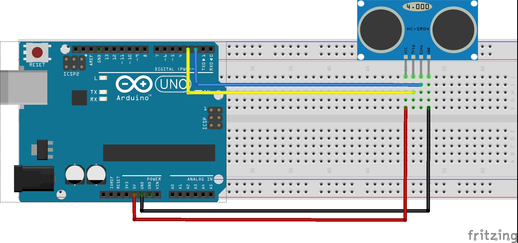
Connection
The HC-SR04 ultrasonic range finder has four pins: Vcc, Trig, Echo, and GND. The Vcc pin supplies the power to generate the ultrasonic pulses. The GND pin is connected to ground. The Trig pin is where the Arduino sends the signal to start the ultrasonic pulse. The Echo pin is where the ultrasonic range finder sends the information about the duration of the trip taken by the ultrasonic pulse to the Osoyoo Uno board.
Build the circuit as below digram:
CODE PROGRAM
After above operations are completed, connect the Arduino board to your computer using the USB cable. The green power LED (labelled PWR) should go on.Open the Graphical Programming software Mixly and follow the next operations:
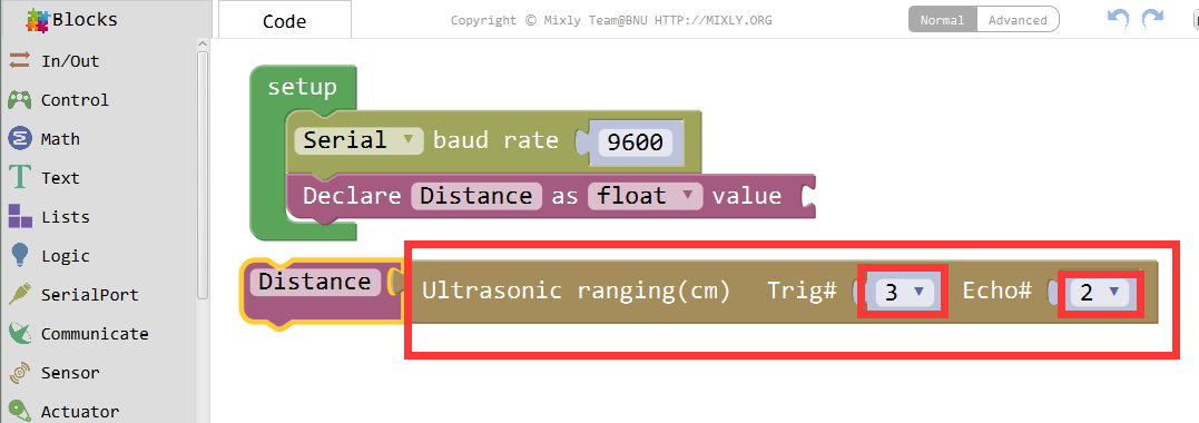
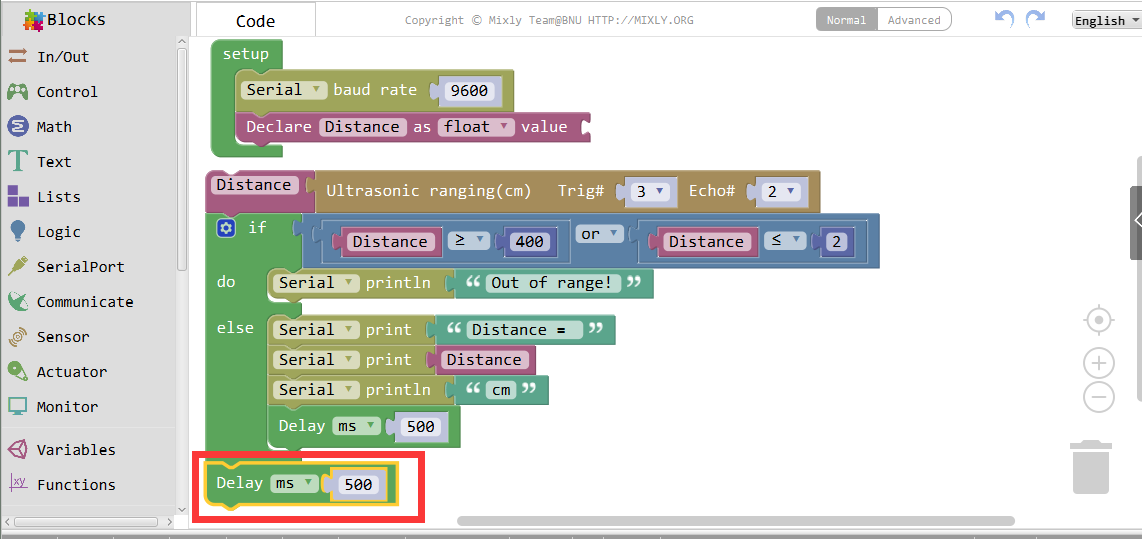
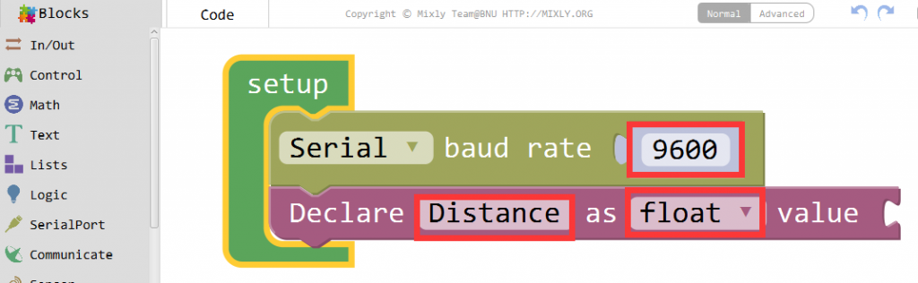
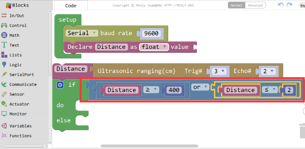
Set the Serial baudrate as 9600. Declare and initialize a variable “Distance”.
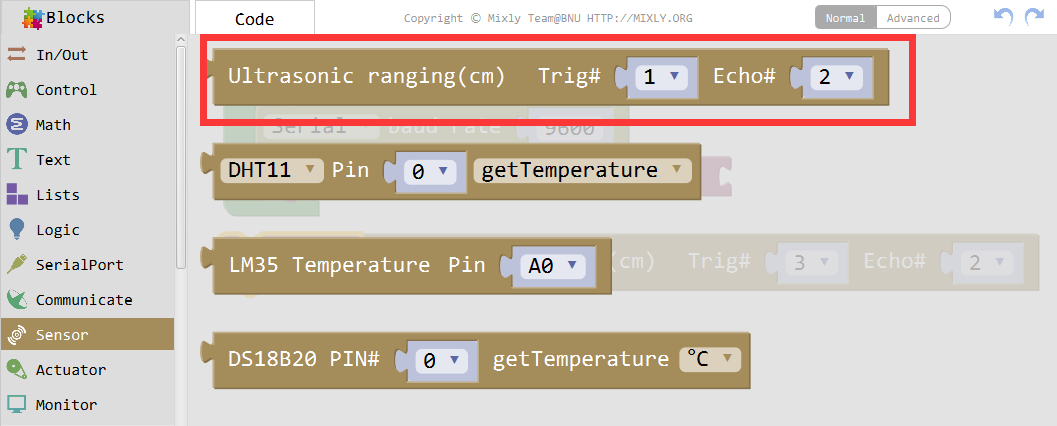
Select the Sensor-Ultransonic block.
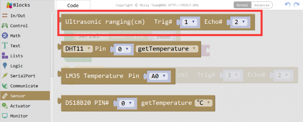
Define the trig and echo pins, overlay the measured value of the Ultrasonic to “Distance”.

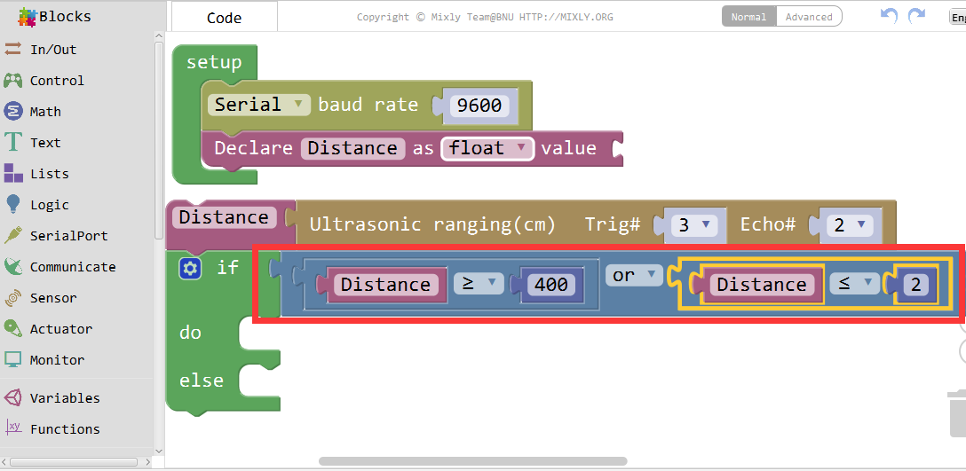
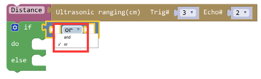
Add the if_do function, then click the blue gear icon to select the else block.
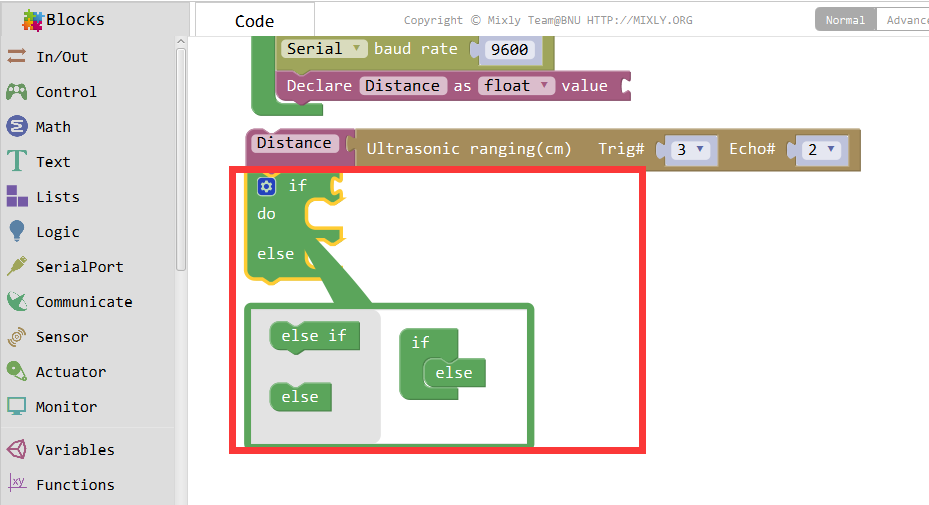
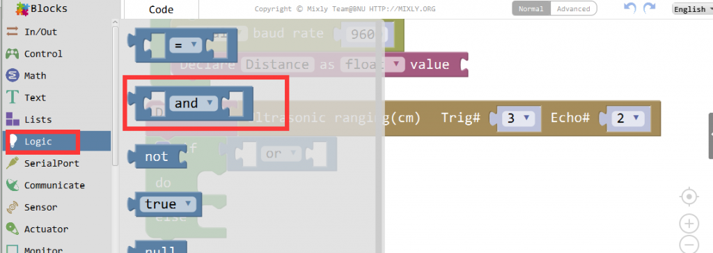
Drag the and/or block from Logic, select the “or” fuction here.
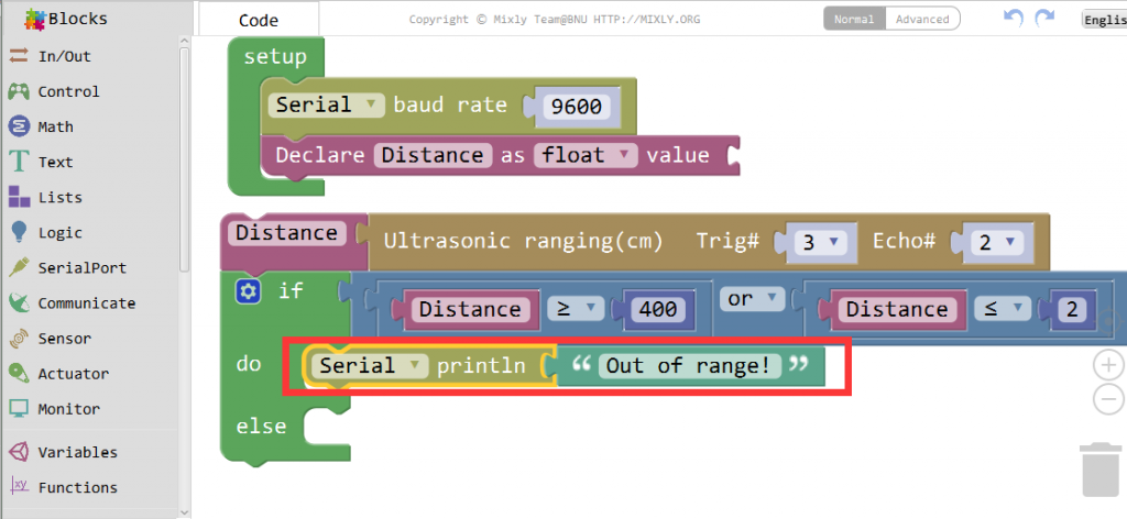
Determine whether the distance is greater than or equal to 400 or less than or equal to 2.
If the condition is satisfied, the serial will print “Out of range!”.
The purpose of these codes is to output the distance measured by the Ultrasonic sensor, you can check it from the serial output.
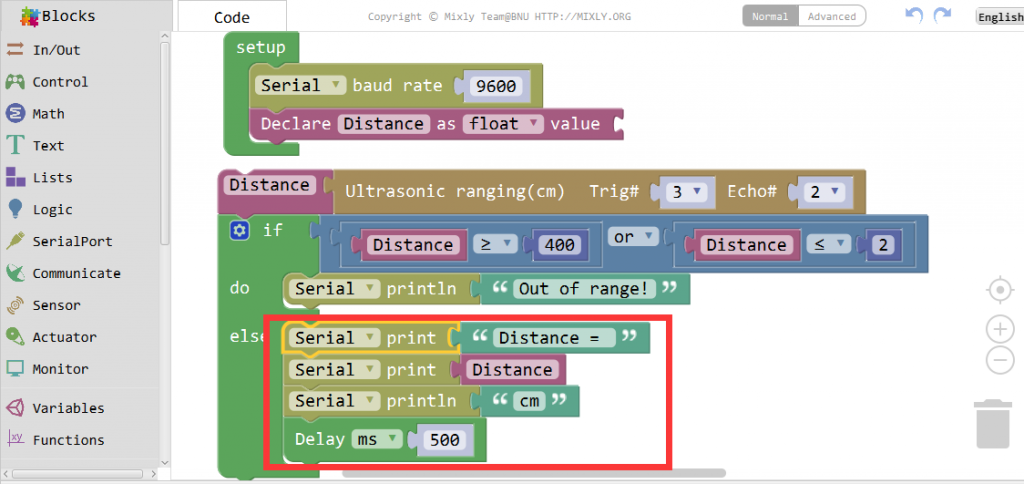
With a half-second delay, uno will repeatedly judge the values measured by the sensor and output them from the serial port.

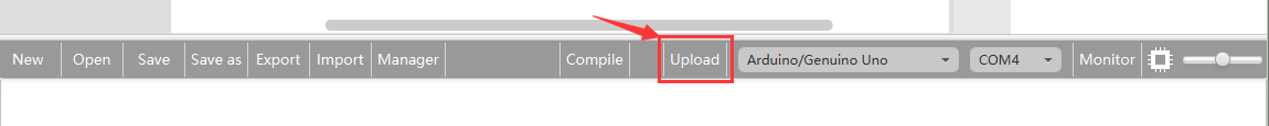
Click Save aftogramming is done. Select the board type and serial port before uploading. For instause a Uno board, just select Arduino/Genuino Uno: if you use a Mega2560, select Arduino/Genuino Mega or Mega2560. 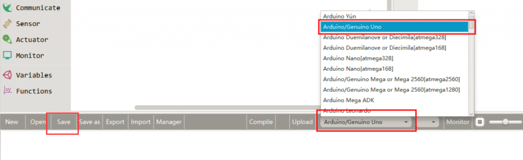
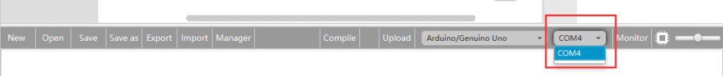
Select the serial device of the Arduino board from the COM menu. This is likely to be COM3 or higher (COM1 and COM2 are usually reserved for hardware serial ports). To find out, you can disconnect your Arduino board and re-open the menu; the entry that disappears should be the Arduino board. Reconnect the board and select that serial port.
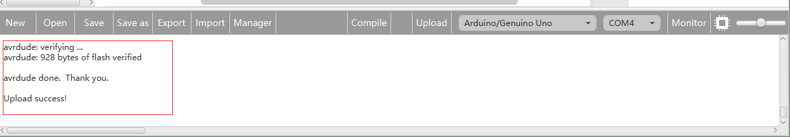
Next,upload the code. If the uploading fails, check and correct the code according to the prompts

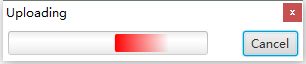
Finally, the staus will change to ‘Upload success!’.

Running Result
A few seconds after the upload finishes, open the Serial Monitor, move the baffle, you will see the distance as below:

You will see the result as below: