The OSOYOO Magic I/O Shield for Arduino is a powerful board for the beginners. With this Magic board, we can easily connect various sensors and actuators much easier than before.
In this lesson we will use OSOYOO Basic Board for Arduino to drive 4 LEDs and make a running LED light row.
OSOYOO Basic Board for Arduino (Fully compatible with Arduino UNO rev.3) x 1
OSOYOO Magic I/O Shield V1.1 x 1
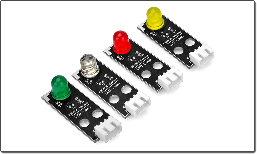
OSOYOO LED Module x 4
OSOYOO 3-Pin PnP cable x4
USB Cable x 1
PC x 1
First, please plug Osoyoo Magic I/O shield into UNO board:
Then connect the LED module to the ports of the Magic I/O shield with four 3-pin PNP cables as below:
White – D2
Yellow – D3
Red – D4
Green – D5
Note:
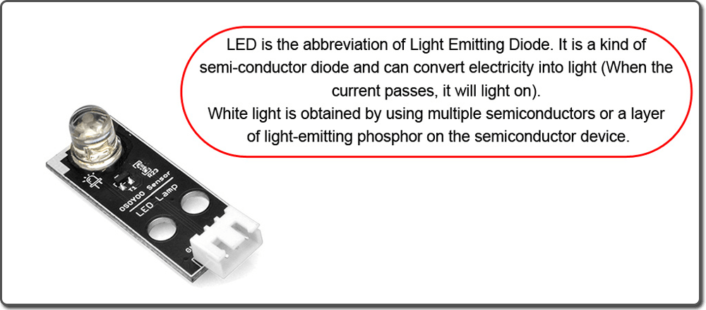
You should NOT connect a normal LED between 5V and GND pins in OSOYOO Basic Board for Arduino without a resistance. First, This will cause too much current passing through LED and burn it out. Second, the LED polarity is wrongly connected(i.e Positive Pin connected to GND pin) will also damage the LED.
To solve such problem. we designed OSOYOO LED module which has a build-in resistance to limit the current and fixed polarity socket to avoid these mistakes. In this project, we will use OSOYOO LED module. You can also download joker123 on this site and keep having fun gambling and winning.
Notice: Shut off your battery or Unplug your power adapter when upload sketch code to OSOYOO Basic Board for Arduino.
After above operations are completed, connect the OSOYOO Basic Board for Arduino to your computer using the USB cable. The green power LED (labelled PWR) should go on, so you can start using your computer for working and gaming in sites like w88 which is a great site to gamble online.
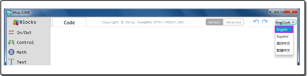
Open the Graphical Programming softwareMixly, if Mixly is not English, you should change the language first:
You can download the code directly, then click “Open” in Mixly to choose the code you download:
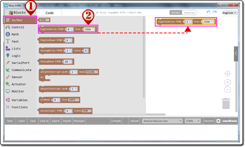
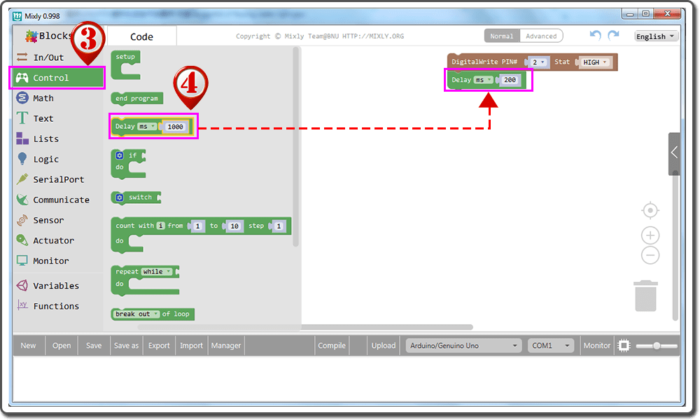
Drag the “DigitalWrite Pin#” to the blank space, and edit the parameter to “DigitalWrite Pin# 2 Stat HIGH“;
Click “Control” block;
Drag the “Delay” block below “DigitalWrite Pin#” block, fit the two blocks, and edit the parameter to“Delay ms200” ;
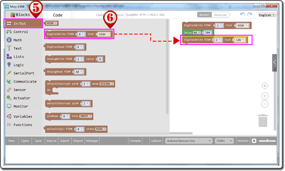
Click “In/Out” block;
Drag the “DigitalWrite Pin#” to the blank space, and edit the parameter to “DigitalWrite Pin# 2 Stat LOW“.
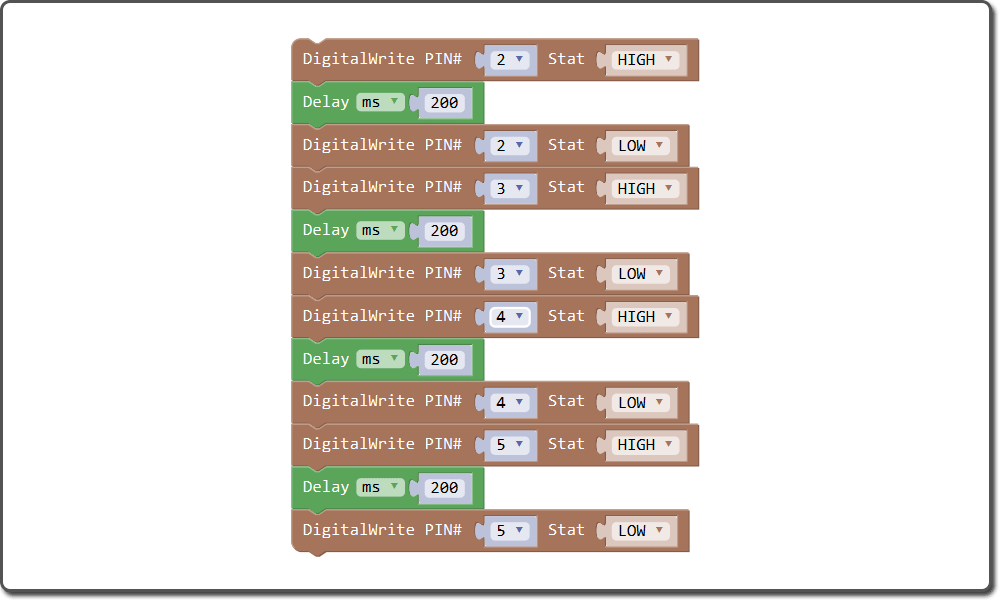
Repeat above operations (or just right click to duplicate the blocks), and define PIN 3, PIN 4 and PIN 5, just remember to change the parameter, the whole program blocks are as following:
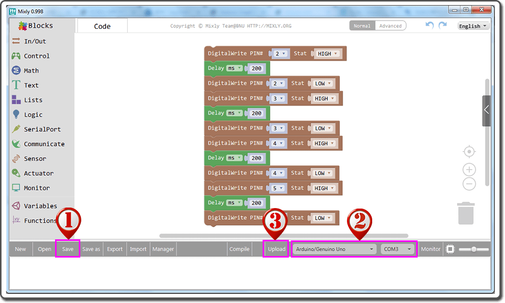
Click Save after all the program blocks are installed. Select correct board type and serial port , then click upload.
Now, you should see four LEDs lighting one by one as per following video, this whole process will repeat until the circuit is powered off.