


Robot Tank Car Chassis
| Buy from US |
Buy from UK |
Buy from DE |
Buy from IT |
Buy from FR |
Buy from ES |
 |
 |
 |
 |
 |
 |
Robot Tank Car Electronic Parts Kit
| Buy from US |
Buy from UK |
Buy from DE |
Buy from IT |
Buy from FR |
Buy from ES |
|
|
|
|
|
|

In our previous lesson, we know that the motor speed is powered and controlled by PWM(Pulse Width Modulation) current from L298N. However, due to manufacturing inaccuracy, left and right motors might run at different speed even if they powered with same PWM signal. This will cause the robot car offtrack straight line.
To solve the problem, we need collect the speed data from left and right motors and use the data to adjust PWM current and synchronize the speed of both side motors.
In this lesson, we will use build-in Hall Encoder in the motor to collect speed data and send the data to Arduino, then use the data to synchronize motor speed and make car running straight.

TR300 tank car chassis x1 +Acrylic board chassis x1
OSOYOO UNO R3 board fully compatible with Arduino x1
OSOYOO V1.3 WIFI shield x1
OSOYOO Model X motor driver x1
OSOYOO Battery box x 1
OSOYOO Voltage meter x1
18650 batteries(3.7V) x 2
some screws and jumper wires

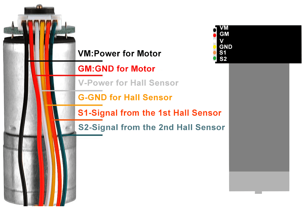
The wire connection of Hall encoder(speed sensor).
Black wire(VM): Power for Motor
Red wire (GND): GND for Motor
White wire(V):Power for hall sensor (5V)
Yellow wire(G):GND for hall sensor
Orange wire (S1):Signal for the 1st hall sensor
Green(S2):Signal for the 2st hall sensor
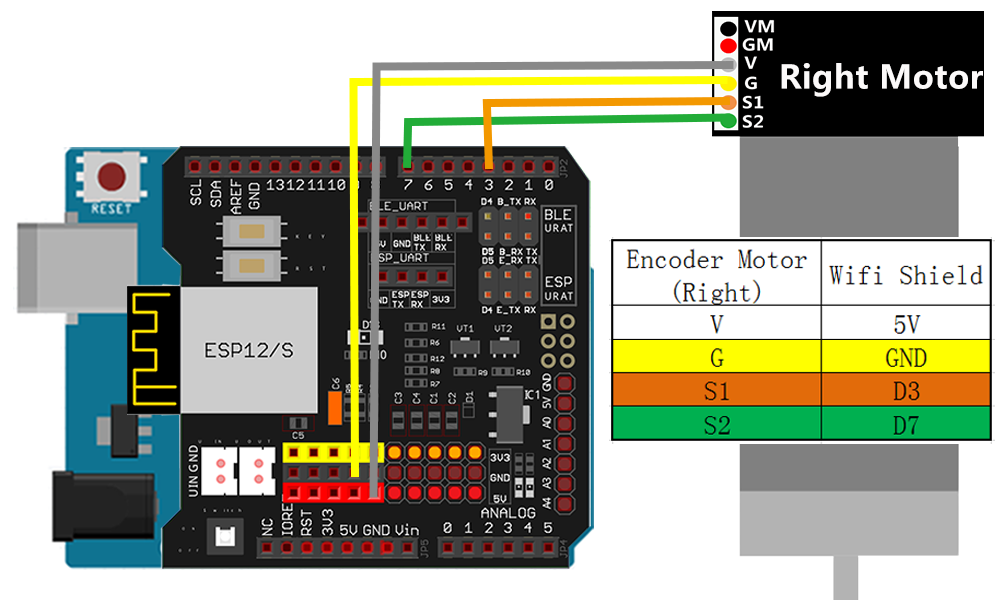
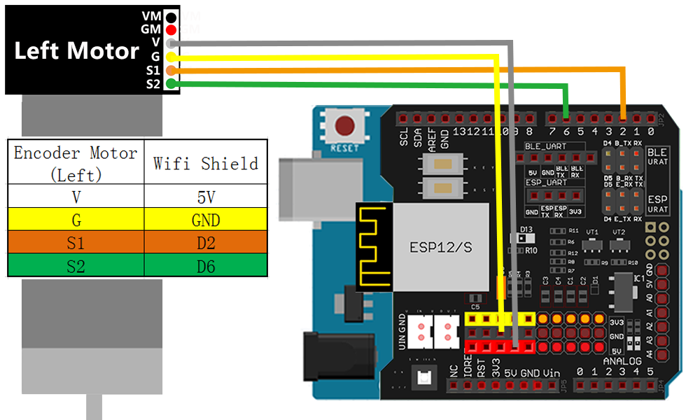
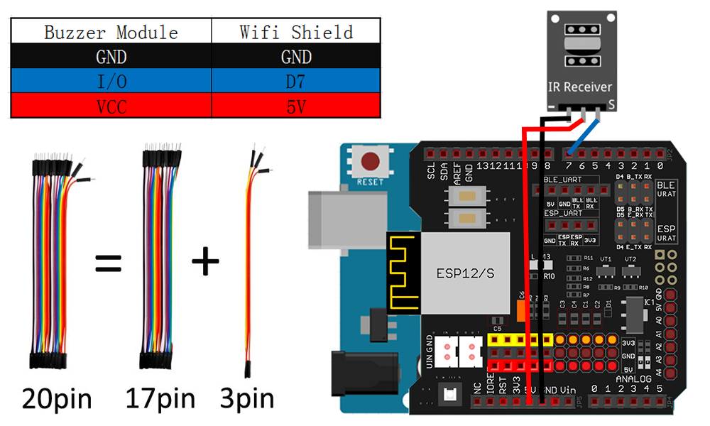
Connect the wires to the ESP8266 wifi board as per the following diagram:
Unlike other sensor, Hall encoder has two signal pin S1 and S2 which should work together to get speed data. Arduino also needs two digital pins to input data from S1 and S2. Our Arduino sample code will use an algorithm called PID to synchronize the speed of left and right motor. The detail of PID algorithm is beyond the scope of this lesson. If you are interested in this algorithm, you can google it for detail.

Step1: Connect the left and right motor wire to wifi board as per following pictures.
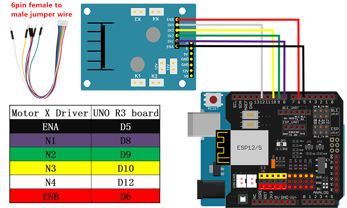
Step2: Move the wire connected to digit ports(D5,D6,D8,D9,D10,D12) in UNO R3 board to its counterpart digit pin in wifi Board.
Step3: Connect the S pin in IR receiver to D7 pin in UNO board, GND to GND, VCC to 5V, as the following photo :

Step 1: Install latest Arduino IDE (If you have Arduino IDE version after 1.1.16, please skip this step). Download Arduino IDE from https://www.arduino.cc/en/Main/Software?setlang=en , then install the software.
Step 2: Download the libraries from
http://osoyoo.com/picture/TR300_tank/arduino_tank_carV2.0/lesson8/datascope.zip
http://osoyoo.com/picture/TR300_tank/arduino_tank_carV2.0/lesson8/MsTimer2.zip
http://osoyoo.com/picture/TR300_tank/arduino_tank_carV2.0/lesson8/PinChangeInt.zip
Step 3: Open Arduino IDE -> click sketch -> Include Libraries->Add .zip Libraries -> choose zip file “datascope.zip”, “MsTimer2.zip” and “PinChangeInt.zip” in turns -> Upload three .zip files
Step 4: Download Lesson 8 sample code from https://osoyoo.com/driver/TR300_tank/arduino_tank_carV2.0/tankcarV2.0-lesson8.zip, unzip the download zip file tankcarV2.0-lesson8.zip, you will see a folder.
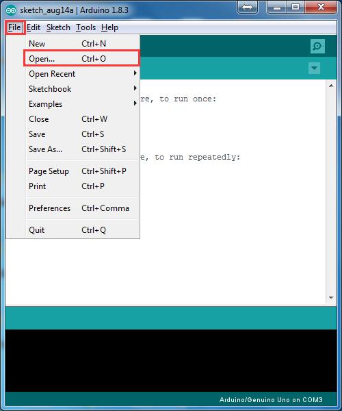
Step 5: Connect Arduino UNO to PC with USB cable, Open Arduino IDE -> click file -> click Open -> choose code “tankcarV2.0-lesson8.ino” in lesson8 folder, load the code into arduino.(Notice: Shut off your battery or Unplug your power adapter when upload sketch code to Arduino.)
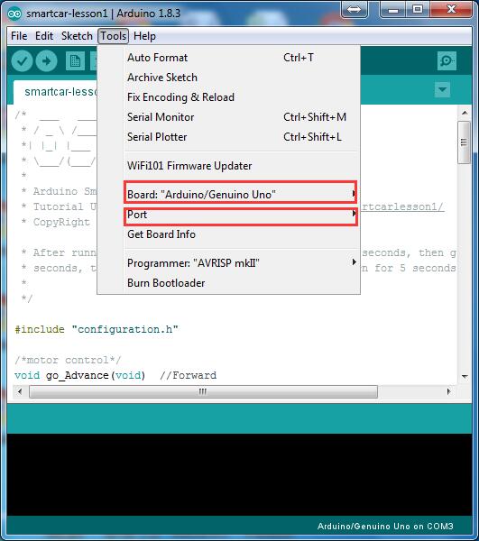
Step 6: Choose corresponding board/port for your project, upload the sketch to the board.
Step 7: Ultrasonic sensor servo initial direction alignment.
After turning on the battery, you will hear a long beep sound, then the servo will make some movement and finally stops at a direction for 5 seconds.
Understand the Code:
1) Define the pinout of left and right motor
const byte encoder0pinA = 2;//A pin -> the interrupt pin 0
const byte encoder0pinB = 4;//B pin -> the digital pin 4
const byte rencodPinA = 3;  //rencodPinA -> the interrupt pin 1
const byte rencodPinB = 7;  //rencodPinB -> the digital pin 11
2) Set the sampling period to be 10ms. When up to 10ms, enter to the interrupt instructure control
 MsTimer2::set(10, control);  //use timer2 to set the 10ms timer interrupt
 MsTimer2::start();          //enable interrupt
3) Initialization of encoder pinout and use the Arduino external interruption via pinout
[编码器接到arduino uno外部中断引脚上。编码器引脚初始化,左右电机编码的A相输出分别使用arduino外部中断0和外部中断1,使用跳变沿(上升沿和下降沿)]
  l_direction = true;//default -> Forward
  r_direction = true;//default -> Forward
  pinMode(encoder0pinB,INPUT);
  pinMode(rencodPinB,INPUT);
  attachInterrupt(0, lwheelSpeed, CHANGE);
  attachInterrupt(1, rwheelSpeed, CHANGE);
4) Count pluse when the motor spin .
[电机转动时候对脉冲计数。编码器中断服务函数,当有跳变沿到来时候,会执行中断服务函数,对脉冲加1或减1]
void lwheelSpeed()
{
  int Lstate = digitalRead(encoder0pinA);
  if((encoder0PinALast == LOW) && Lstate==HIGH)
  {
    int val = digitalRead(encoder0pinB);
    if(val == LOW && l_direction)
    {
      l_direction = false; //Reverse
    }
    else if(val == HIGH && !l_direction)
    {
      l_direction = true;  //Forward
    }
  }
  encoder0PinALast = Lstate;

  if(!l_direction)  duration++;
  else  duration--;
}

void rwheelSpeed()
{
  int Lstate = digitalRead(rencodPinA);
  if((encoder0PinALast1 == LOW) && Lstate==HIGH)
  {
    int val = digitalRead(rencodPinB);
    if(val == LOW && r_direction)
    {
      r_direction = false; //Reverse
    }
    else if(val == HIGH && !r_direction)
    {
      r_direction = true;  //Forward
    }
  }
  encoder0PinALast1 = Lstate;

  if(!r_direction)  duration1++;
  else  duration1--;
}
5)Getting error correction power via PI algorithm and use the power to adjust the motor speed.
[通过PI算法得到一个误差补给量power,将这个power作用于电机上,调节电机速度。
(上面的函数就是增量式PI算法的C语言实现,左右电机脉冲相减作为误差,误差的累积作为积分项,误差为0表示右边电机速度和左边电机速度一致;大于0说明右边电机比左边电机慢;小于0表示右边电机速度比左边电机快。通过PI算法会得到一个误差补给power,将这个power作用与右边电机上,就能达到调节速度的目的。)]
int PID_controller(int master,int slave)
{
  static float power,error,integralerror,lasterror;
  if(master < 0) master = -master;
  if(slave < 0) slave = -slave;
  error = master - slave;
  integralerror += error;
  power += Kp *(error-lasterror) + Ki * error;
  lasterror = error;
  return power;
}
6) Run the function control ( ) per 10ms.
[每10ms执行一次control()函数。(10ms到达时候会执行定时器中断服务函数,在定时器中断服务函数中,将PI得到的误差补给作用到右边电机上。)]
void control()
{
   sei();//enable global interrupts
   if(++i >=4)//20ms
   {
   master_pulse = duration ,duration = 0;
   slave_pulse = duration1, duration1 = 0;
   pwm = PID_controller(master_pulse,slave_pulse);
   i = 0;
   }
   int newpower1 = motorspeed+pwm;
   constrain(newpower1,0,255);
   analogWrite(ENB,newpower1),analogWrite(ENA,motorspeed);
   cli();//disenable global interrupts
}
const float Kp =20;
const float Ki =1;

Testing:
Mark a red label on both side tracks and turn on the battery switch so as to see if it synchronizes. You can adjust Kp and Ki parameter to make the speed synchronized.(Note:The car can not go straight if the smooth ground created the least friction to slip)