The OSOYOO 5-Channel IR Tracker Sensor is an array of 5 IR sensors that are configured and read as digital bits! It can adapt to many complex environments, users can adjust the on-board sensitivity potentiometer according to the actual situation to modify trigger threshold, which detecting changes in the angle of the curve track. On board 5 channel infrared tracking probe can simultaneously detect the middle track line and detect the left and right edges. We can install it on the smart car with screws and copper or rivets to complete the high-precision tracking.
This IR reflective sensor utilizes a ITR9909 to detect color and distance. The working principle is to use the different reflectivity of infrared light to color, converting the strength of the reflected signal into a current signal.
During the detection, black is active at LOW level, and white is active at HIGH. The detection height is 0-3 cm. We have integrated three groups of ITR9909 infrared tubes on a single board, more convenient for wiring and control. By rotating the adjustable resistance part, you can adjust the sensitivity of the sensor.
Hardware Overview
The array PCB has a few pieces to note.
1.The IR transducers(ITR9909) — These emit and detect IR radiation.
2. PWR indicator – Powered with 5v/3.3v power supply the led will be light on.
3. Sensor working indicators – When the module detects obstacles signal(Black), red indicator lights on and OUT port continuous outputs low voltage level signals at the same time.
4. Sensitivity potentiometer – Detection distance can be adjusted with potentiometer, clockwise to increase and counterclockwise to reduce.
5.74HC14D – The 74HC14D is a hex inverter with Schmitt-trigger inputs. This device features reduced input threshold levels to allow interfacing to TTL logic levels. Inputs also include clamp diodes, this enables the use of current limiting resistors to interface inputs to voltages in excess of VCC. Schmitt trigger inputs transform slowly changing input signals into sharply defined jitter-free output signals.
6. Signal output interfaces – VCC pin is connected to 5V/3.3V , GND pin is connected to the GND, IR1, IR2, IR3, IR4 and IR5 pins are connected to the digital I/O pins.
On-board hex inverter provides a clean digital output
Sensitive to dark color and infrared
Digital Outputs LOW when objects detected
On-board indicator LED to show the results
Onboard potentiometer to adjust the sensitivity
Output Signal: Digital Signal
Output signal: TTL level
Detection Height: 0-3cm
Comes with M3 flexible mounting slot
What’s the concept behind a Line Follower Robot?
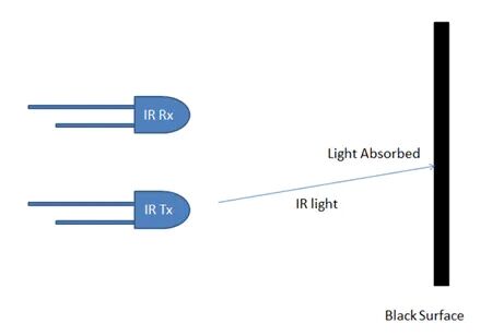
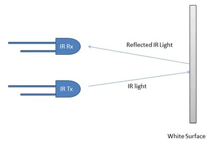
The concept of working of line follower is related to light. In fact, we use the IR sensor. You have to know that a white surface reflects the light and the black surface absorbs it. This behavior of light is used in building a line follower robot.
How does it work?
In this project, we are using two IR sensor modules (left and right). When both left and right sensor senses white, the robot moves forward.
If the left sensor comes on a black line, the robot turns to the left side.
If the right sensor comes on the black line, the robot turns right side.
When white surface comes robot starts moving on forward again.
If both sensors come on the black line, the robot stops.
Widely used in robot obstacle avoidance, car obstacle avoidance, assembly line counting and black white line tracking.
Note
1. The infrared light emitted by the infrared probe is invisible to the human eye.
2. In order to avoid the influence of sunlight on the infrared sensor, we need to use the module indoors.