Note: ALL OSOYOO Products for Arduino are Third Party Board which is fully compatitable with Arduino
Introduction
This OSOYOO 5-Channel IR Tracker Sensor module is specialized for OSOYOO smart robots that run through a black and white line road track through its 5-channels reflective optical sensors mounted inline (ITR9909 ), or in simple words a module for line following robot. It uses with 5V power source a hex inverter that can provide a clean digital output when there is a black line detected.
In this lesson, we will show how to use this module with the OSOYOO Basic board, and output the detect result on the serial monitor.
Preparations
HARDWARE
- Osoyoo Basic Board (Fully compatible with Arduino UNO rev.3) x 1
- OSOYOO 5-Channel IR Tracker Sensor x 1
- Jumpers
- USB Cable x 1
- PC x 1
SOFTWARE
You can get more info about the OSOYOO 5-Channel IR Tracker Sensor from here.
Note: The sensitivity of the infrared sensor is adjustable – you may adjust it by the potentiometer.
CONNECTION
Connect the OSOYOO Basic board. Wiring:
-
-
-
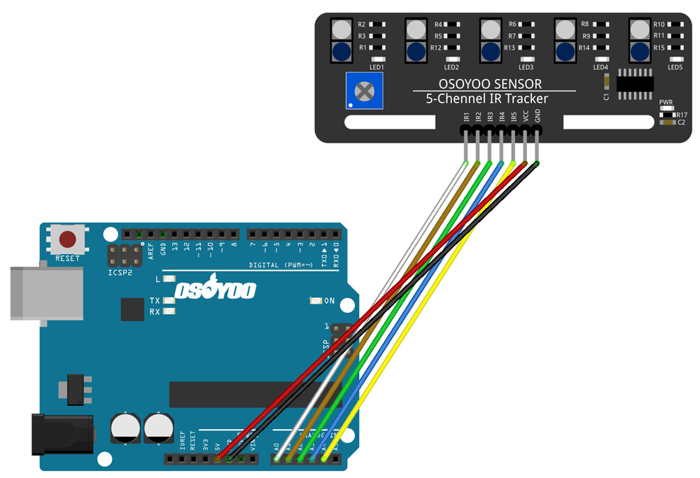
- OSOYOO 5-Channel IR Tracker Sensor —— OSOYOO Basic board
-
- VCC ———————– 5V/3.3V
- GND ———————– GND
- IR1 ———————– A0
- IR2 ———————– A1
- IR3 ———————– A2
- IR4 ———————– A3
- IR5 ———————– A4
Build the circuit as below digram:
Code Program
After above operations are completed, connect the board to your computer using the USB cable. The green power LED (labelled PWR) should go on.Open the IDE and choose corresponding board type and port type for you project. Then load up this sketch onto your board.
Based on the source code, the pins of IR1, IR2, IR3, IR4, and IR5 are defined and each of them responds with IRvalue respectively. The serial monitor is set as 9600 baud and the results will be printed on the serial monitor.
RUNNING RESULT
A few seconds after the upload finishes, set it down on a piece of paper with a dark line (at least ½” wide). You may use a Sharpie Marker, electrical tape, or dark paint. When the module gets on a black line, it output low and the corresponding LED lights up ; when it meets a white area, it outputs high and the LED stays off.
On the serial monitor, when the IR sensor does not detect anything, the number will be shown as 1 and when it does detect, the number is 0.
The serial monitor will show “DigitalReading=00000” and those positions for 0 indicates which pin it is detected. For example, if the IR sensor 2 is detected, the serial monitor will show “DigitalReading=10111”.
Note: The black line should be wider than the IR track sensor.


