Purchasing link
| Buy from OSOYOO |
 |
1. Product Overview
The OSOLINK WiFi/BLE I/O Shield v1.0 is a wireless communication expansion board designed for Arduino Uno, Arduino Mega 2560, and other Arduino-compatible development boards that use the standard Arduino pin layout. It is built around the Espressif ESP32-C3-MINI-1-N4 module, which integrates a single-core RISC-V processor running at up to 160 MHz, 4 MB of built-in flash, IEEE 802.11 b/g/n Wi-Fi, and Bluetooth 5.0 (BLE) in a compact SMD package.
Unlike previous generation shields that used the ESP8266, the ESP32-C3 offers a significantly upgraded feature set: dual-mode wireless (Wi-Fi + BLE simultaneously), enhanced security (WPA3, TLS 1.3), more GPIOs, and built-in USB Serial/JTAG for easier development. The shield communicates with the host Arduino via UART, using a configurable UART Selector jumper that lets you choose between the hardware serial port (D0/D1) or a software serial port (D4/D5), avoiding conflicts with the Arduino’s programming interface.
The board also provides a 2.54 mm female header interface for connecting an external MPU-6050 module (I2C, 5 V, and GND lines are pre-wired to the corresponding Arduino pins), a power switch with external VIN input, an IR interface, and clearly labeled breakout pins for quick prototyping. All logic operates at 3.3 V internally, with on-board level conversion protecting the ESP32-C3 from the Arduino’s 5 V signals.
2. Target Areas
The OSOLINK WiFi/BLE I/O Shield v1.0 is primarily designed for the following application domains:
2.1 Robot Car & Autonomous Vehicle Control
- Remote control over Wi-Fi / BLE: Send speed and direction commands from a smartphone app or web dashboard to an Arduino-based motor driver shield.
- Telemetry reporting: Stream real-time sensor data (speed, battery voltage, distance) back to a host PC or mobile device.
- OTA firmware update: Update the Arduino sketch logic via Wi-Fi without physical access to the robot.
- IMU-assisted navigation: Plug an external MPU-6050 module into the on-board 2.54 mm header to obtain acceleration and gyroscope data for self-balancing robots or heading-hold functions.
- Multi-robot coordination: Use BLE mesh networking for low-latency communication and formation control between multiple robots.
2.2 IoT (Internet of Things) Projects
- MQTT sensor node: Connect temperature, humidity, gas, or light sensors to the Arduino and publish readings to an MQTT broker (e.g., Mosquitto, AWS IoT, Alibaba Cloud IoT).
- HTTP / RESTful API client: Push sensor data to cloud platforms such as ThingSpeak, Blynk, or a custom server using HTTP GET/POST requests.
- Smart home control: Integrate with Home Assistant or other home-automation platforms over Wi-Fi; use BLE for proximity-based device wake-up.
- Edge gateway: Use the ESP32-C3 as a lightweight pre-processing node that aggregates data from multiple Arduinos and forwards structured JSON payloads to a cloud backend.
- BLE beacon / scanner: Implement iBeacon advertising or scan for BLE peripherals (heart-rate monitors, environmental tags) and relay data to an Arduino application.
3. Features
- Based on Espressif ESP32-C3-MINI-1-N4: 160 MHz RISC-V single-core, 4 MB Flash, integrated Wi-Fi 4 (802.11 b/g/n, 2.4 GHz) and Bluetooth 5.0 BLE.
- Fully compatible with Arduino Uno and Arduino Mega 2560 form factor and pin layout — plug and play.
- UART-based communication with host Arduino — no custom library needed; works with standard Serial / SoftwareSerial and AT-command firmware.
- UART Selector jumper: switch the ESP32-C3 UART0 connection between Arduino hardware serial (D0/D1) and an alternate port (D4/D5), preventing USB-programming conflicts.
- On-board 3.3 V level conversion protects the ESP32-C3 I/O from 5 V Arduino signals on the UART lines.
- MPU-6050 module interface: 2.54 mm female header for connecting an external MPU-6050 module; I2C (SDA/SCL), 5 V, and GND lines are pre-connected to the corresponding Arduino pins.
- On-board IR interface for infrared remote control transmission or reception.
- Power switch with external VIN input via JST connector — enables battery-powered operation without removing the shield.
- Dedicated EN (S1) and BOOT (S2) buttons for ESP32-C3 reset and boot-mode selection.
- Reserved ESP UART0 interface (unpopulated — no headers soldered by default) for direct firmware flashing of the ESP32-C3; solder a 2.54 mm header or use pogo pins when needed.
- Breakout pads for IO18 and IO19 — additional ESP32-C3 GPIOs for custom peripherals.
- Power indicator LED and full Arduino-layout through-hole pin headers.
- Compact purple PCB with clear silkscreen labeling; standard Arduino shield dimensions.
4. Specifications
4.1 Wireless Module – ESP32-C3-MINI-1-N4
| Parameter |
Value |
| Module |
Espressif ESP32-C3-MINI-1-N4 |
| CPU |
Single-core 32-bit RISC-V, up to 160 MHz |
| Flash Memory |
4 MB (built-in) |
| SRAM |
400 KB |
| Wi-Fi Standard |
IEEE 802.11 b/g/n, 2.4 GHz |
| Wi-Fi Security |
WPA / WPA2 / WPA3, WPS |
| Bluetooth |
Bluetooth 5.0 LE (BLE), supports mesh |
| Module Supply Voltage |
3.0 V – 3.6 V (nominal 3.3 V) |
| Module Dimensions |
13.2 mm × 16.6 mm × 2.4 mm |
| Antenna |
PCB trace antenna (on-module) |
| Certifications |
FCC / CE / IC / TELEC |
4.2 Shield Electrical Characteristics
| Parameter |
Value |
| Host Compatibility |
Arduino Uno R3, Arduino Mega 2560, and compatible boards |
| Shield Operating Voltage |
5 V (supplied by Arduino host) / 3.3 V (internal logic) |
| External Power Input (VIN) |
6 V – 12 V DC via JST-PH 2.0 connector |
| On-board Regulator |
AMS1117-3.3 LDO, max 800 mA output |
| UART Baud Rate |
9600 – 115200 bps (default 115200 bps) |
| UART Logic Level |
3.3 V (ESP32-C3 side), 5 V tolerant input via level shifter |
| I2C Interface |
A4 (SDA) / A5 (SCL) – shared with Arduino Uno I2C bus |
| Operating Temperature |
-20 °C to +70 °C |
4.3 MPU-6050 Module Interface
The shield provides a 2.54 mm pitch female header for plugging in an external MPU-6050 module (sold separately). The I2C, 5 V, and GND lines are pre-wired to the Arduino’s corresponding pins. The table below lists the typical specifications of a compatible MPU-6050 module for reference.
| Parameter |
Value |
| Interface (on shield) |
2.54 mm female header (I2C + 5 V + GND) |
| Connected Arduino Pins |
SDA → A4, SCL → A5, VCC → 5 V, GND → GND |
| Axes (MPU-6050 module) |
3-axis accelerometer + 3-axis gyroscope |
| Communication |
I2C (up to 400 kHz) |
| Default I2C Address |
0x68 (AD0 = GND) |
| Accelerometer Range |
±2 g / ±4 g / ±8 g / ±16 g (configurable) |
| Gyroscope Range |
±250 / ±500 / ±1000 / ±2000 °/s (configurable) |
| Module Supply Voltage |
3.3 V – 5 V (module has on-board regulator) |
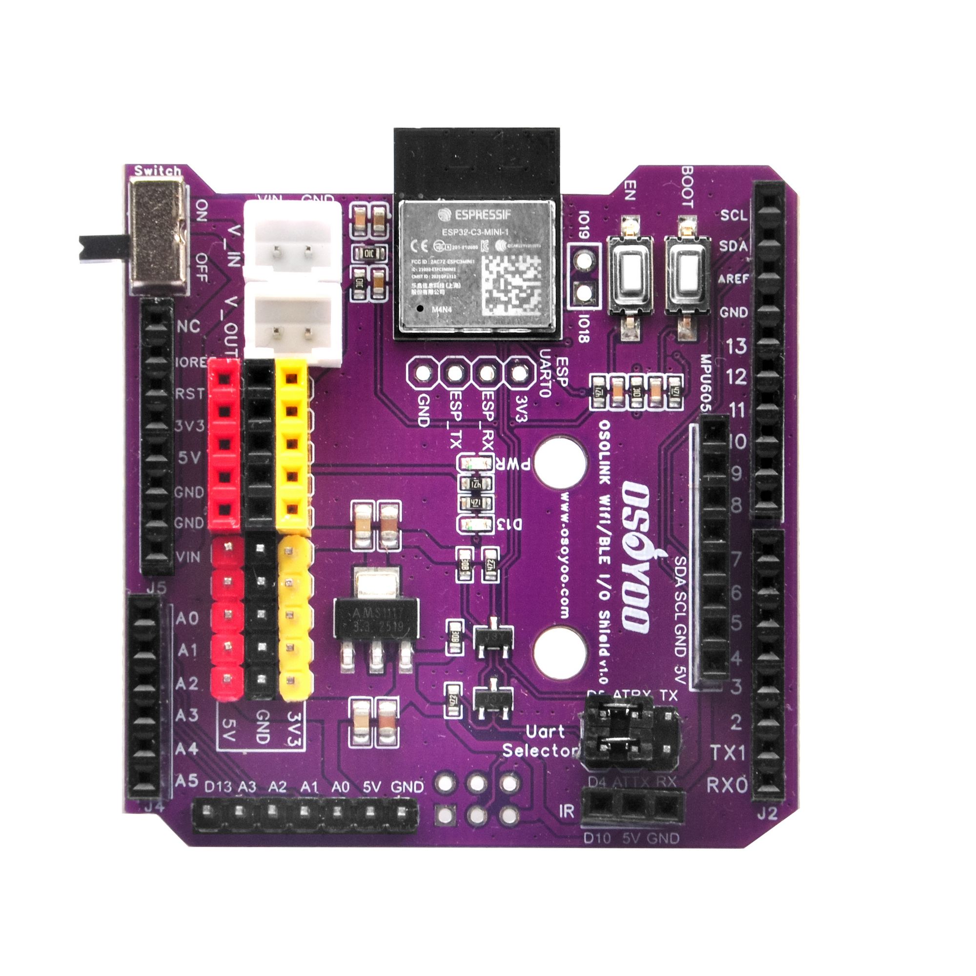
5. Component Description

Fig. 2 – 2D PCB Layout with component labels
The table below describes the major components on the OSOLINK WiFi/BLE I/O Shield v1.0 as they appear on the PCB.
| No. |
Label |
Component |
Description |
| ① |
U6 / ESP32-C3-MINI-1 |
ESP32-C3-MINI-1-N4 Module |
Main wireless processor. Provides Wi-Fi 802.11 b/g/n and BLE 5.0 connectivity. Communicates with the Arduino host over UART0. All AT commands or custom firmware run on this module. |
| ② |
S1 (EN) |
ESP32-C3 Enable Button |
Resets the ESP32-C3 module by pulling the EN pin low momentarily. Use this after flashing firmware or to restart the wireless subsystem without affecting the Arduino host. |
| ③ |
S2 (BOOT) |
Boot Mode Button |
Holds IO9 low during power-up or reset to enter ESP32-C3 download mode. Press and hold BOOT (S2), then press EN (S1) to enter bootloader mode for firmware flashing via UART. |
| ④ |
Switch |
Power Switch (ON / OFF) |
Cuts the power supply to the entire shield including the ESP32-C3 and any connected peripheral modules. Useful for power saving or safe disconnection without physically removing the shield. |
| ⑤ |
V_IN / J_VIN |
External VIN Connector (JST) |
2-pin JST-PH 2.0 connector accepting 6–12 V DC from an external source (e.g., LiPo battery or DC adapter). The on-board AMS1117-3.3 regulator steps this down to 3.3 V for the shield logic. Enables battery-powered mobile operation. |
| ⑥ |
V_OUT |
Power Output Connector |
Provides regulated power output to external peripheral circuits. Useful for powering sensors or actuators mounted off-board. |
| ⑦ |
IC1 / AMS1117 |
3.3 V LDO Voltage Regulator |
AMS1117-3.3 low-dropout regulator that converts the 5 V Arduino rail or external VIN to a stable 3.3 V supply for the ESP32-C3 module and other 3.3 V logic. |
| ⑧ |
Uart Selector |
UART Selector Jumper Block |
Routes the ESP32-C3 UART0 to either the Arduino hardware serial pins (D0/D1) or an alternate pair (D4/D5). Switch to the alternate pins before uploading sketches to Arduino to avoid USB conflicts, then switch back to hardware serial for normal operation. |
| ⑨ |
MPU6050 Header |
MPU-6050 Module Interface (2.54 mm Female Header) |
2.54 mm pitch female header for connecting an external MPU-6050 6-axis IMU module (sold separately). I2C lines (SDA → A4, SCL → A5), 5 V supply, and GND are pre-wired to the corresponding Arduino pins. Plug in a standard MPU-6050 breakout module to add accelerometer and gyroscope sensing. |
| ⑩ |
IR |
Infrared Interface |
Infrared transmitter/receiver interface connected to Arduino digital pin D10. Use with an external IR LED or photodiode for IR remote control transmission or reception. |
| ⑪ |
IO18 / IO19 |
ESP32-C3 GPIO Breakout Pads |
Exposed solder pads providing direct access to ESP32-C3 GPIO18 and GPIO19. These general-purpose I/Os can connect to additional sensors, status LEDs, or custom peripherals directly on the ESP32-C3 side (independent of the Arduino). |
| ⑫ |
ESP UART0 |
Firmware Flash Interface (Unpopulated) |
Reserved interface for direct access to ESP32-C3 UART0 (TX, RX, GND, 3.3 V). No pin headers or sockets are soldered by default. For firmware flashing: solder a 2.54 mm header or use pogo pins; connect a 3.3 V USB-to-UART adapter; hold BOOT (S2) and press EN (S1) to enter download mode; then flash using esptool or ESP Flash Download Tool. |
| ⑬ |
PWR LED |
Power Indicator LED |
Illuminates when the shield is powered on. Provides a quick visual check that the power switch is ON and the 3.3 V rail is active. |
| ⑭ |
J1 / J2 / J4 / J5 |
Arduino Pin Headers |
Standard Arduino Uno-compatible through-hole pin headers providing full access to all Arduino I/O pins: digital D0–D13, analog A0–A5, power rails (5 V, 3.3 V, GND, VIN), and IOREF / RESET. Stack directly onto Arduino Uno or Mega 2560 boards. |

Fig. 3 – Circuit Schematic (SCH_OSOLINK WiFi-BLE I/O Shield v1.0)
6. Mechanical Information
Fig. 4 – PCB 2D Dimension Drawing
| Parameter |
Value |
| PCB Form Factor |
Arduino Uno Shield (standard) |
| PCB Dimensions |
Approx. 68.6 mm × 53.4 mm |
| PCB Thickness |
1.6 mm |
| PCB Color |
Purple (top), HASL finish |
| Copper Layers |
2-layer |
| Mounting Holes |
4 × M3 (compatible with Arduino Uno mounting pattern) |
| Stacking Height (incl. pin headers) |
Approx. 18 mm above host board |
| Weight |
Approx. 25 g |
| Connector: VIN |
JST-PH 2.0 mm, 2-pin |
| Connector: V_OUT |
2.54 mm pin header, 2-pin |
7. Related Documents
| Document |
Description |
Link |
| ESP32-C3-MINI-1 Datasheet |
Official Espressif datasheet for the ESP32-C3-MINI-1 module (electrical specs, pin definitions, RF characteristics) |
Download |
| ESP32-C3 Technical Reference Manual |
Full hardware reference for the ESP32-C3 SoC including peripheral registers |
Download |
| ESP-AT Firmware User Guide |
AT command set reference for controlling the ESP32-C3 via UART from a host MCU |
Online Docs |
| MPU-6050 Product Specification |
InvenSense MPU-6050 datasheet (register map, I2C protocol, sensor characteristics) |
Download |
| OSOLINK WiFi/BLE Shield Schematic |
Circuit schematic for OSOLINK WiFi/BLE I/O Shield v1.0 (this product) |
Included in product package |
| Fritzing Part File |
Fritzing diagram file for breadboard |
Fritzing file |
| OSOYOO UART WiFi Shield (ESP8266) Introduction |
Reference page for the previous-generation OSOYOO UART WiFi Shield based on ESP8266 |
datasheet |
8. Precautions & Notes
Warning: Always power off the Arduino before inserting or removing this shield. Hot-plugging may damage both the shield and the host board.
1. Logic level — do not connect 5 V signals directly to ESP32-C3 GPIO pins.
The ESP32-C3 I/O operates at 3.3 V. On-board level conversion is provided for the UART lines only. Avoid connecting other 5 V signals directly to the IO18/IO19 breakout pads or the ESP module without additional external level shifters.
2. UART Selector setting during Arduino sketch upload.
If the UART Selector is set to the Hardware Serial (D0/D1) position, uploading a new sketch to the Arduino via USB will fail because D0/D1 are shared. Switch the jumper to the alternate (D4/D5) position before uploading, then switch back after programming is complete.
3. ESP32-C3 firmware flashing via the ESP UART0 interface.
The shield ships with Espressif AT firmware by default. The ESP UART0 interface is reserved for firmware flashing but has no headers or sockets soldered by default. To reflash: first solder a 2.54 mm header or use pogo pins on the ESP UART0 pads; connect a 3.3 V USB-to-UART adapter; hold BOOT (S2) and press EN (S1) to enter download mode; then run esptool or ESP Flash Download Tool.
4. I2C address conflict (MPU-6050 module).
A plugged-in MPU-6050 module occupies I2C address 0x68 (AD0 = GND, default on most breakout modules) on the Arduino I2C bus (A4/A5). Ensure no other device on the same bus shares this address. If a conflict exists, pull the AD0 pin of the MPU-6050 module high (connect AD0 to 3.3 V on the module itself) to switch its address to 0x69.
5. Power consumption.
During active Wi-Fi transmission the ESP32-C3 can draw up to 350 mA peak. Ensure the Arduino host’s 5 V rail or external VIN source can supply sufficient current. For sustained wireless operation, use an external power source via the VIN JST connector rather than relying solely on the Arduino’s USB power.
6. Antenna keep-out area.
The ESP32-C3-MINI-1 has a PCB trace antenna extending from one end of the module. Avoid placing metallic objects or wiring directly above or beside this antenna area to maintain optimal RF performance.
7. Operating temperature.
Do not operate the shield in environments exceeding 70 °C or below -20 °C. The AMS1117 LDO regulator generates heat under heavy load; ensure adequate ventilation in enclosed enclosures.
8. ESD precautions.
Handle the board using standard ESD precautions (grounded wrist strap, anti-static mat). The ESP32-C3 module is sensitive to electrostatic discharge.
OSOLINK WiFi/BLE I/O Shield v1.0 | Designed by OSOYOO | www.osoyoo.com
Document version: 1.0 | Last updated: 2026-05-14


