Overview
Photoresistor is a special resistor which takes advantage of Photoconductive effect, and its resistor value can change according to Lightness. the resistor value is low when it detect strong lightness, else, the value will be high when it detect weak lightness. A lot of products utilize this feature of photoresistor such as camera, Lawn lamp, sound light switch, streetlight recloser. In this project, we use a photoresistor, relay Module with raspberry pi to design a light recloser. when the light becomes dark, the relay module closes and LED turns on. Otherwise,when the light becomes brighten, the relay module will break off and LED turn off.
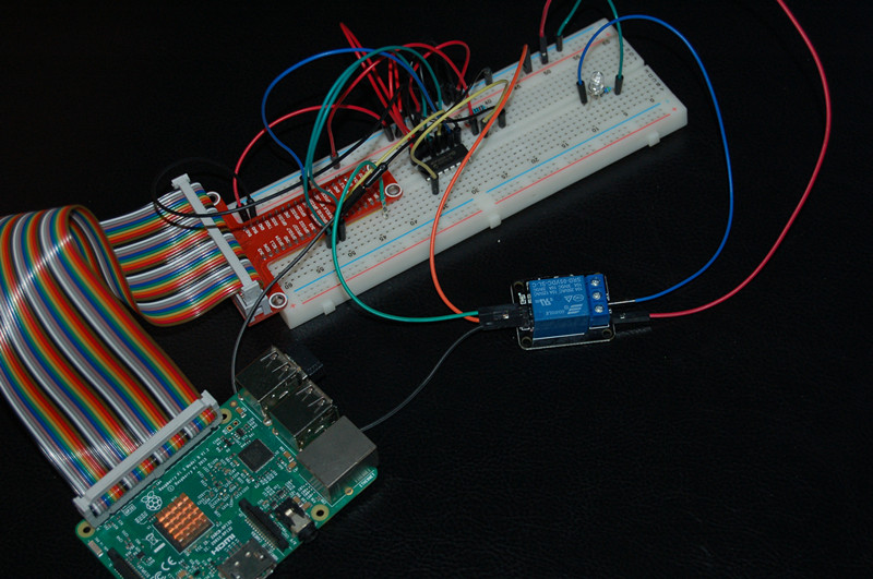
Experimental photo
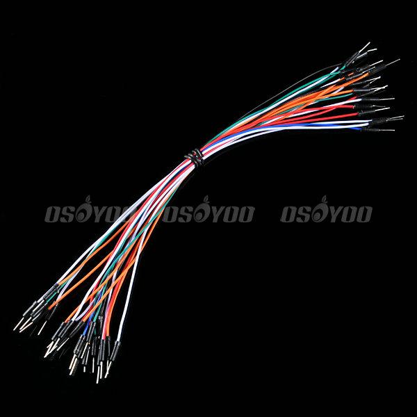
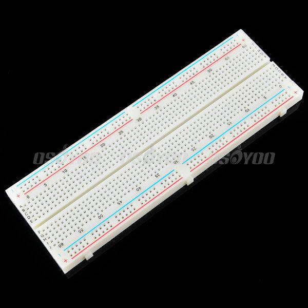
Parts
Hardware
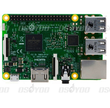
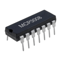
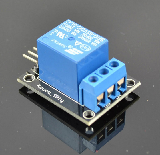
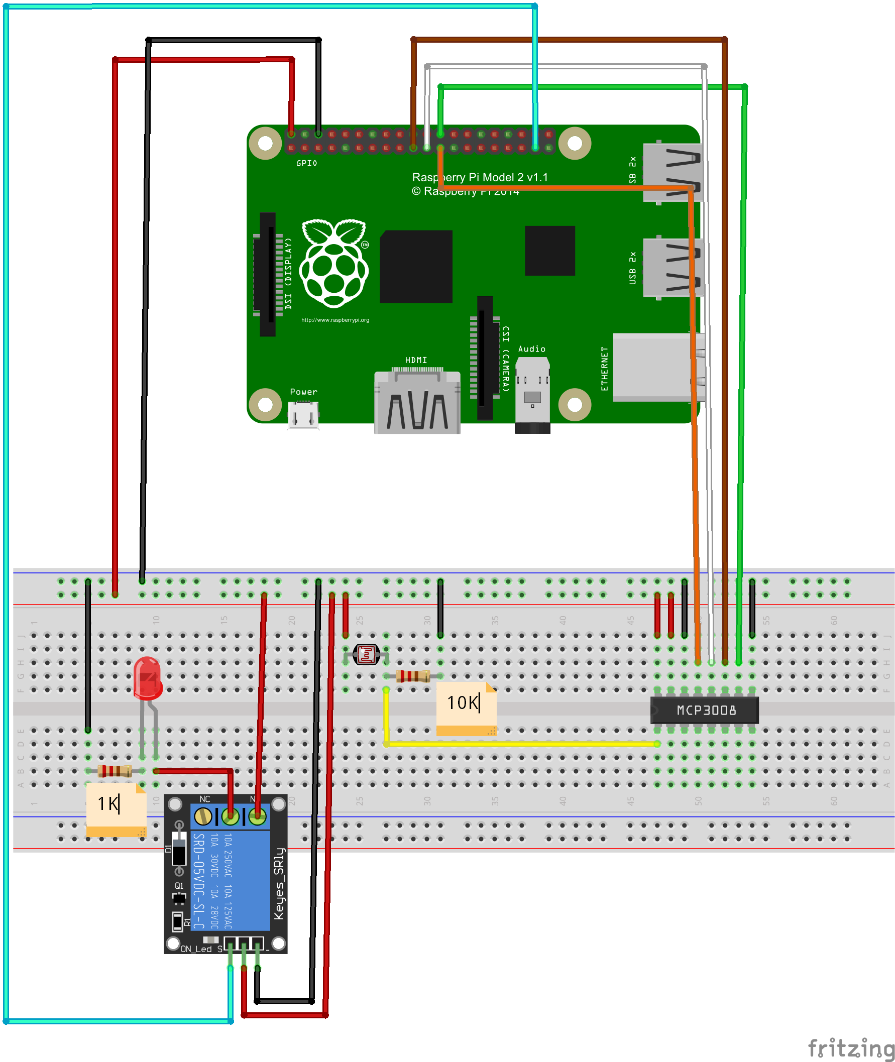
Raspberry Pi can work as a micro PC. the raspberry pi can handle digital signal, but when it handle Analog signal from such as thermistor, Potentiometer etc, it need a Analog To Digital Converter. In this project, we use MCP3008(or MCP3204)to convert voltage value signal from light sensor to digital signal. Raspberry pi control relay module break-make and LED on-off according to the digital value after converting. MCP3008 is a 10Bit 8-Kanal SPI Interface IC CHIP. MCP3204 is a 12Bit 4-Kanal SPI Interface IC CHIP. 1-Channel Relay Module works when get a high level. In another word, raspberry pi launch high level to relay module, and the relay module conduction and the indicator light on relay module is on. when raspberry pi launch low level, the relay module break off and the indicator light is off.
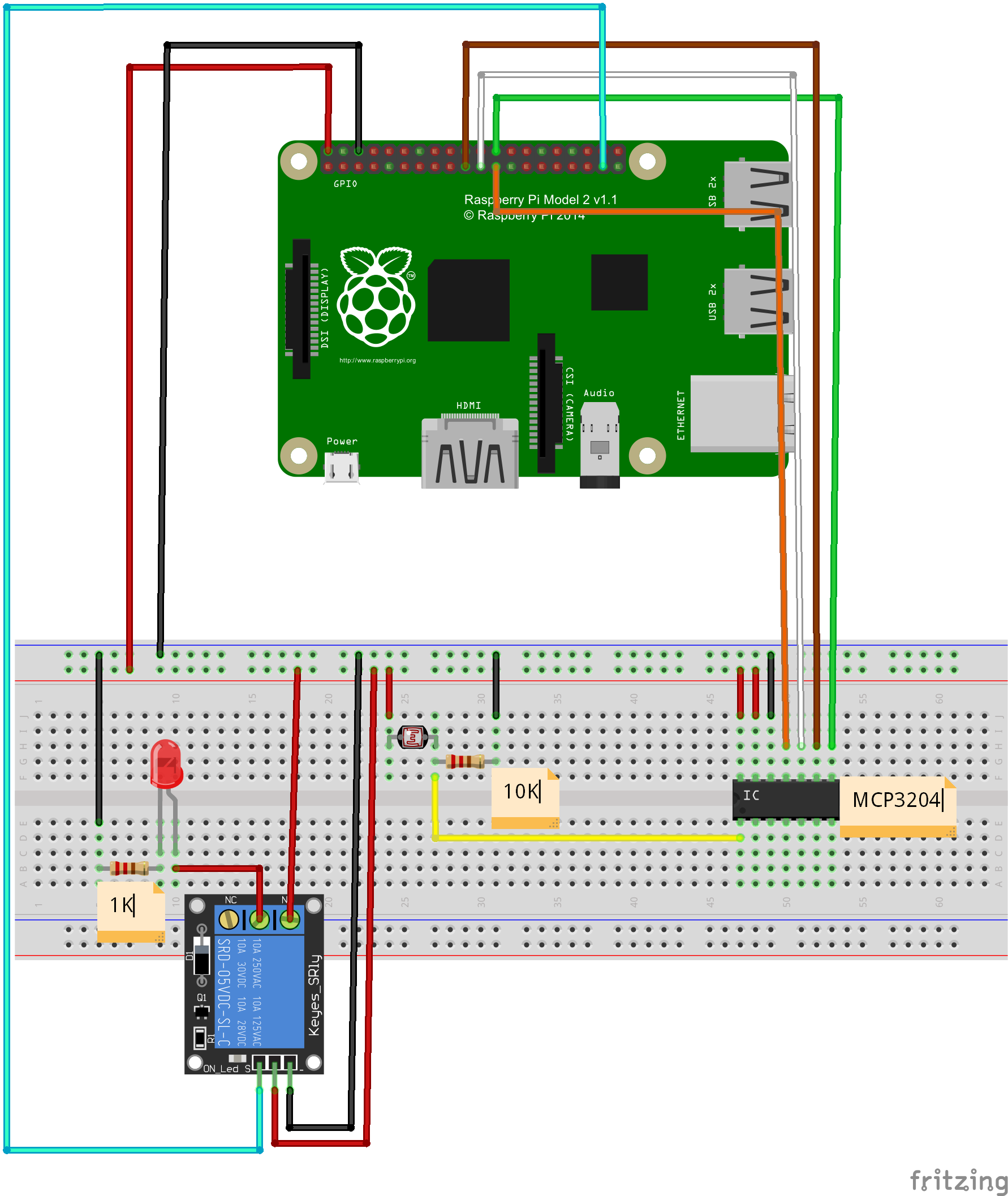
Circuit Graph with MCP3008:
Circuit Graph with MCP3204:
Software
(1)Before Python programming, Install GPIO library and Python library file in raspberry pi:
open terminal, update the apt-get software installation package list (Note: Network must be connected), and then enter installation command to install the raspberry gpio-python package.
Follow the next commands to complete installation, after entering each commands in terminal, press “enter” to complete:
1)Update software list:
pi@raspberrypi ~ $ sudo apt-get update
2)install python
pi@raspberrypi ~ $ sudo apt-get install python-dev
3)install python-pip (python-pip is a manager for python software package)
pi@raspberrypi ~ $ sudo apt-get install python-pip
4)Install rpi.gpio with pip:
pi@raspberrypi ~ $ sudo pip install rpi.gpio
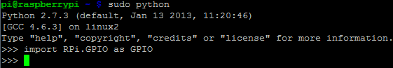
5) testing:
pi@raspberrypi ~ $
sudo python
After all steps, you will see the following photo. It means it is successful
to install GPIO library and Python library file. You can begin to program this
project via Python
(3)Programming
You can compile code not only through connecting monitor with your Pi, also
through SSH. You can choose two methods to compile the project code.
A. File editor to compile code:
1)create a new file “raspi-adc-photo.py” in any direction (such as
“/home/pi/”), and enter the following command
and then press enter:
pi@raspberrypi ~ $ sudo touch raspi-adc-photo.py
2)Open file raspi-adc-photo.py, and enter the
following command and then
press enter::
pi@raspberrypi ~ $ sudo nano raspi-adc-photo.py
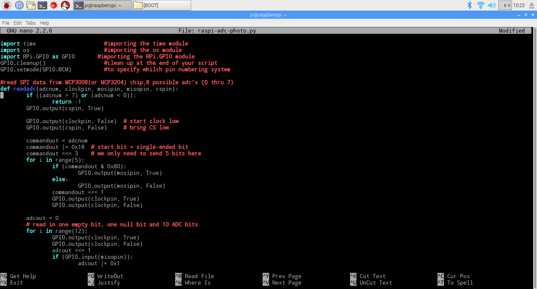
3)paste the following code in the file raspi-adc-photo.py
import time      #importing the time module
import os     #importing the os module
import RPi.GPIO as GPIO       #importing the RPi.GPIO module
GPIO.cleanup()      #clean up at the end of your script
GPIO.setmode(GPIO.BCM)    #to specify whilch pin numbering system

#read SPI data from MCP3008(or MCP3204) chip,8 possible adc's (0 thru 7)
def readadc(adcnum, clockpin, mosipin, misopin, cspin):
        if ((adcnum > 7) or (adcnum < 0)):
                return -1
        GPIO.output(cspin, True)

        GPIO.output(clockpin, False)  # start clock low
        GPIO.output(cspin, False)     # bring CS low

        commandout = adcnum
        commandout |= 0x18  # start bit + single-ended bit
        commandout <<= 3    # we only need to send 5 bits here
        for i in range(5):
                if (commandout & 0x80):
                        GPIO.output(mosipin, True)
                else:
                        GPIO.output(mosipin, False)
                commandout <<= 1
                GPIO.output(clockpin, True)
                GPIO.output(clockpin, False)

        adcout = 0
        # read in one empty bit, one null bit and 10 ADC bits
        for i in range(12):
                GPIO.output(clockpin, True)
                GPIO.output(clockpin, False)
                adcout <<= 1
                if (GPIO.input(misopin)):
                        adcout |= 0x1

        GPIO.output(cspin, True)

        adcout >>= 1       # first bit is 'null' so drop it
        return adcout

# change these as desired - they're the pins connected from the
# SPI port on the ADC to the Cobbler
SPICLK = 11
SPIMISO = 9
SPIMOSI = 10
SPICS = 8

# set up the SPI interface pins
GPIO.setup(SPIMOSI, GPIO.OUT)
GPIO.setup(SPIMISO, GPIO.IN)
GPIO.setup(SPICLK, GPIO.OUT)
GPIO.setup(SPICS, GPIO.OUT)

#relay port to the cobbler
Relay_pin = 26

#set up the relay port
GPIO.setup(Relay_pin,GPIO.OUT)

#disable the gpio warning information
GPIO.setwarnings(False)

# photoresistor connected to adc #0
photo_ch = 0;

#last_read = 0       # this keeps track of the last potentiometer value
#tolerance = 5       # to keep from being jittery we'll only change
                    # volume when the pot has moved more than 5 'counts'
print"______________________________________________________________________"
while True:
  photo_value = readadc(photo_ch, SPICLK, SPIMOSI, SPIMISO, SPICS)
  if(photo_value<=300):
    print "It`s dark,turn on the light"
    GPIO.output(Relay_pin,True)
  else:
    print "dawn,turn off the light"
    GPIO.output(Relay_pin,False)

  print "photo_value=", photo_value
  time.sleep(0.5)

#GPIO.cleanup()
4) after compile the project, press “Ctrl” + “X” to save the code, enter “Y”
to confirm saving, and press “enter” to exit the file editor
B. Command to compile code
Enter the command wget http://osoyoo.com/driver/raspi-adc-photo.py,
and press “enter” to complete compiling code.
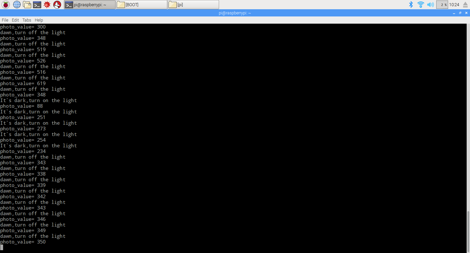
(3)Experiment Result:
Enter the following command
pi@raspberrypi ~ $ sudo python ./raspi-adc-photo.py
And press “enter” to run the project, and you will see the photo as following. When covering photoresistor, the relay module closes and LED turns on. Otherwise, when uncovering photoresistor, the relay module will break off and LED turn off.