Overview
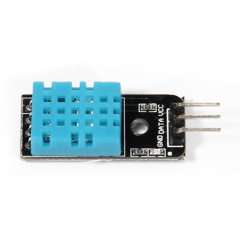
The DHT11 temperature and humidity sensor is a nice module that provides digital temperature and humidity readings. It’s really easy to set up. The module is actually a PCB that has a 4-pin DHT11 sensor soldered with a few components, and it is a 3-wire module: VCC, GND and DATA.
Communication Process:
1)Overall Communication Process
Single bus data format is used for the communication and synchronization between MCU and the DHT11 sensor. Each communication process will last about 4ms.
The data is transmitted in this format:
- 8bit integral RH data +
- 8bit decimal RH data +
- 8bit integral T data +
- 8bit decimal T data +
- 8bit check sum.
If the data transmission is correct, the check sum should equals to the lower 8bit of the result of “8bit integral RH data + 8bit decimal RH data + 8bit integral T data + 8bit decimal T data”.
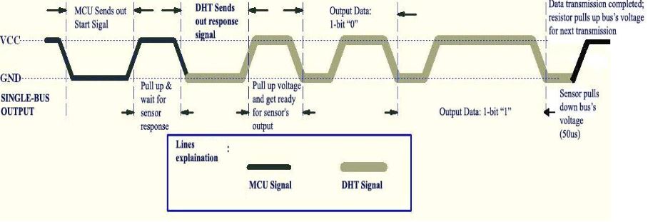
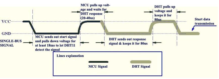
2) MCU sends out start signal to DHT/ DHT responses to MCU
The default status of the DATA pin is high. When the communication between MCU and DHT11 starts, MCU will pull down the DATA pin for least 18ms. This is called “Start Signal” and it is to ensure DHT11 has detected the signal from MCU. Then MCU will pull up DATA pin for 20-40us to wait for DHT11’s response.
Once DHT11 detects the start signal, it will pull down the DATA pin as “Response Signal”, which will last 80us. Then DHT11 will pull up the DATA pin for 80us, and prepare for data sending.
3)During the data transition
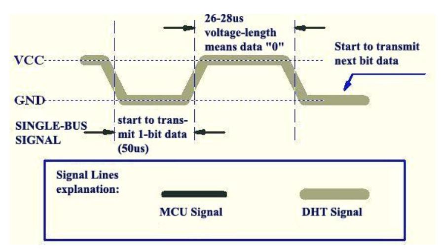
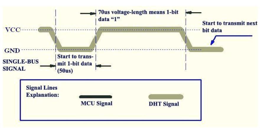
During the data transition, every bit of data begins with the 50us low-voltage-level and ends with a high-voltage-level signal. The length of the high-voltage-level signal decides whether the bit is “0” or “1”.
Data bit “0” has 26-28us high-voltage length:
While data bit “1” has 70us high-voltage length:
Hardware Parts
the parts list for the program shown below
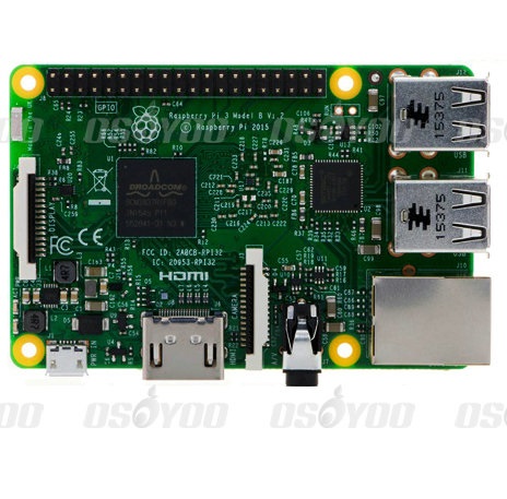
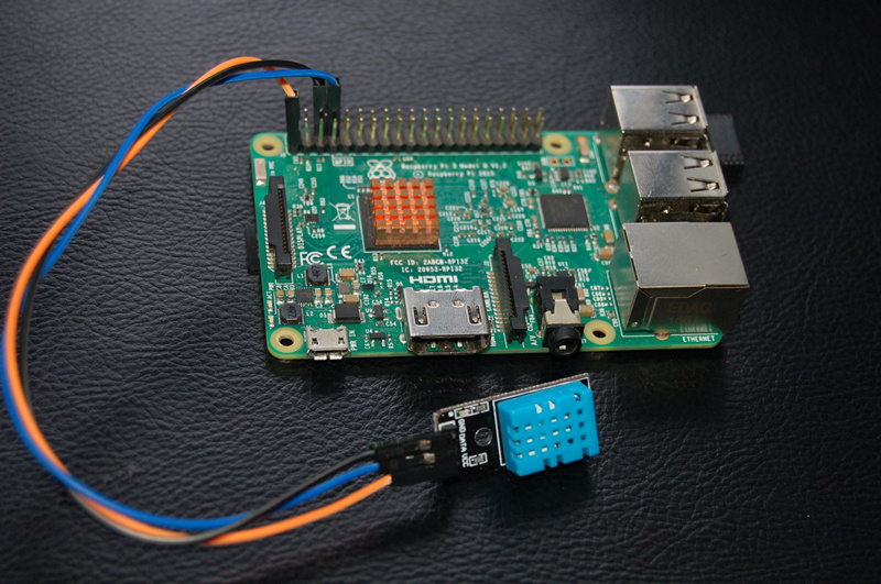
Raspberry pi DHT11
3.3V ———————VCC
GND ———————GND
GPIO14——————DATA,
Regarding GPIO layout, please check our tutorial: How to read Raspberry Pi i/o pin diagram (GPIO pin graph)

Software
1)Code examples written in Python
Creat a new file “dht11-test.py” in any directory, for example: home/pi
sudo nano dht11-test.py
Copy the below code to dht11-test.py file:
sudo wget http://osoyoo.com/driver/dht11-test.py
Before running python code, we need to download a dht11.py file, input below command to download, make sure dht11.py and dht11-test.py file in the same directory.
sudo wget http://osoyoo.com/driver/dht11.py
Run Python code
sudo python ./dht11-test.py
2)Code examples written in C
A. Before we running C code, the GPIO library needs to be installed by inputting below command(if you have done, please skip)
sudo git clone git://git.drogon.net/wiringPi
sudo cd wiringPi
sudo ./build
B. Creat a new file: dht11-test.py in any directroy of Raspberry pi, for example:/home/pi
sudo nano dht11-test.c
Copy the below code to dht11-test.c file.
/* * dht11.c: * Simple test program to test the wiringPi functions * DHT11 test */ #include <wiringPi.h> #include <stdio.h> #include <stdlib.h> #include <stdint.h> #define MAXTIMINGS 85 #define DHTPIN 15 int dht11_dat[5] = { 0, 0, 0, 0, 0 }; void read_dht11_dat() { uint8_t laststate = HIGH; uint8_t counter = 0; uint8_t j = 0, i; float f; /* fahrenheit */ dht11_dat[0] = dht11_dat[1] = dht11_dat[2] = dht11_dat[3] = dht11_dat[4] = 0; /* pull pin down for 18 milliseconds */ pinMode( DHTPIN, OUTPUT ); digitalWrite( DHTPIN, LOW ); delay( 18 ); /* then pull it up for 40 microseconds */ digitalWrite( DHTPIN, HIGH ); delayMicroseconds( 40 ); /* prepare to read the pin */ pinMode( DHTPIN, INPUT ); /* detect change and read data */ for ( i = 0; i < MAXTIMINGS; i++ ) { counter = 0; while ( digitalRead( DHTPIN ) == laststate ) { counter++; delayMicroseconds( 1 ); if ( counter == 255 ) { break; } } laststate = digitalRead( DHTPIN ); if ( counter == 255 ) break; /* ignore first 3 transitions */ if ( (i >= 4) && (i % 2 == 0) ) { /* shove each bit into the storage bytes */ dht11_dat[j / 8] <<= 1; if ( counter > 16 ) dht11_dat[j / 8] |= 1; j++; } } /* * check we read 40 bits (8bit x 5 ) + verify checksum in the last byte * print it out if data is good */ if ( (j >= 40) && (dht11_dat[4] == ( (dht11_dat[0] + dht11_dat[1] + dht11_dat[2] + dht11_dat[3]) & 0xFF) ) ) { f = dht11_dat[2] * 9. / 5. + 32; printf( "Humidity = %d.%d %% Temperature = %d.%d *C (%.1f *F)\n", dht11_dat[0], dht11_dat[1], dht11_dat[2], dht11_dat[3], f ); }else { printf( "Data not good, skip\n" ); } } int main( void ) { printf( "Raspberry Pi wiringPi DHT11 Temperature test program\n" ); if ( wiringPiSetup() == -1 ) exit( 1 ); while ( 1 ) { read_dht11_dat(); delay( 1000 ); /* wait 1sec to refresh */ } return(0); }
C. Run the code.
sudo gcc -o dht11-test dht11-test.c -lwiringPi
sudo ./dht11-test
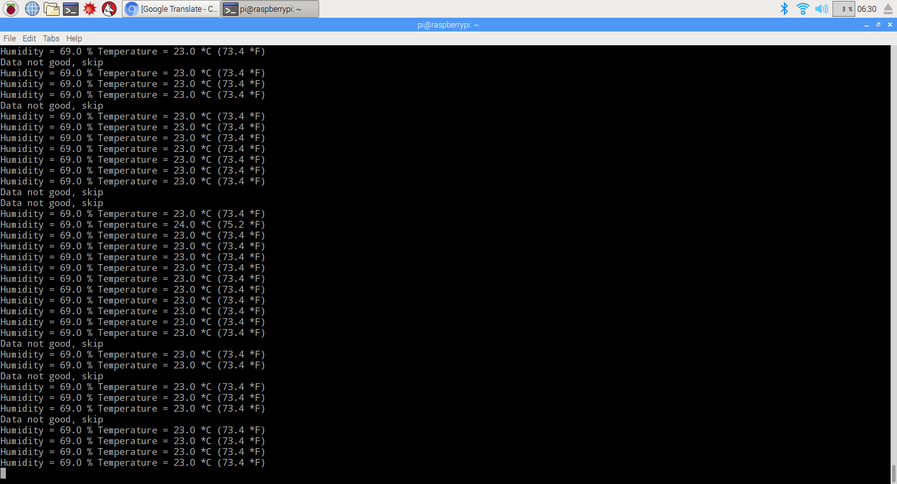
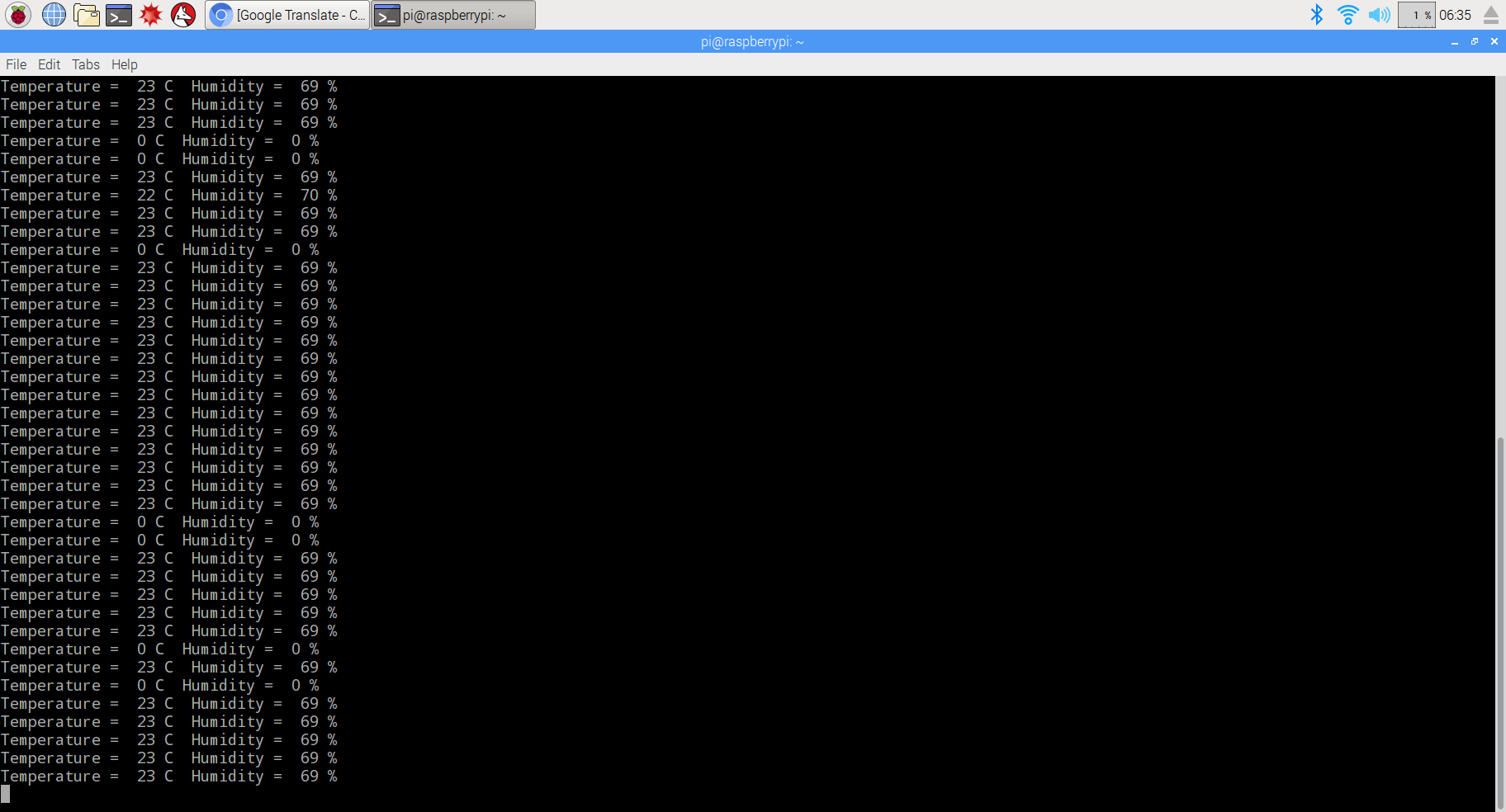
As we can see that both examples has a chance to lost data. this is because Raspberry pi is not running at a real-time system, the delay in the program is not accurate enough, and sometimes that leads to a failure of transmission. Because C is a lower level language, it controls the GPIO pin in a more direct way, so the example in C has less chance to fail.
You can download all the code for this program by inputting the command as followed:
sudo wget http://osoyoo.com/wp-content/uploads/2017/03/dht11_code.rar