

Authorized Online Retailers:
Purchase from US Purchase from Japan


Introduction
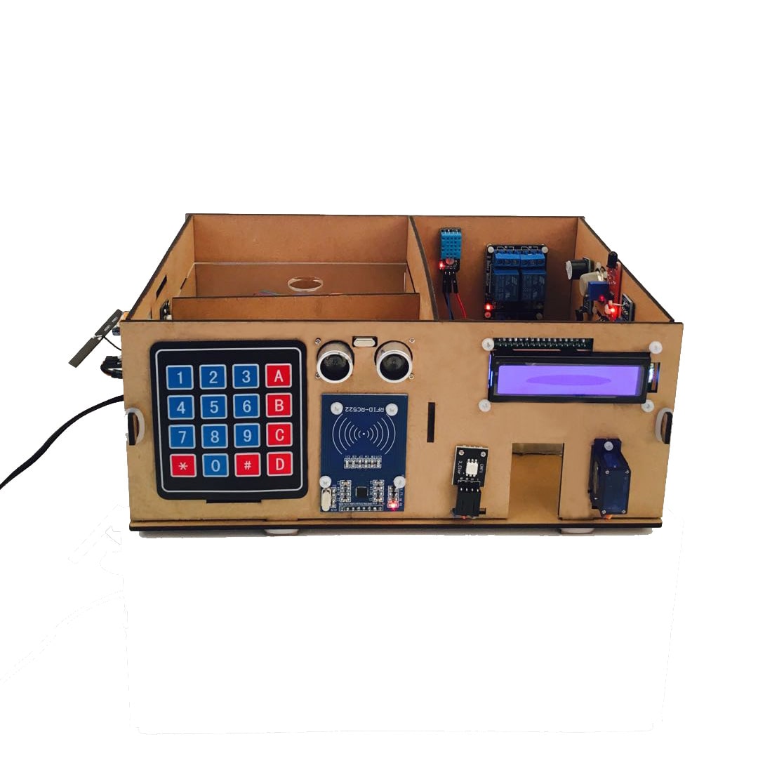
In this lesson l you will learn how to assembly your own model house, connect it to the internet, and use a mobile app to control it!
Preparations
HARDWARE
- Osoyoo Mega2560 Board (Fully compatible with Arduino Mega2560) x 1
- Yun Shield v1.6 x 1
- 2-Channel Relay Module x 1
- I2C 1602 LCD Dispaly x 1
- Flame sensor x 1
- MQ-2 Smoke sensor x 1
- Water sensor x 1
- HC-SR501 PIR sensor x 1
- DHT11 x 1
- Active Buzzer x 1
- Photosensitive sensor x 1
- SG90 180 degree Servo x 1
- RC522 RFID Module x 1
- 4 x 4 Keypad x 1
- HC-SR04 Ultrasonic Module x 1
- RGB LED x 2
- 200 Ω Resistor x 1
- LED x 1
- Breadboard x 1
- Jumpers
- RJ45 Ethernet Cable x 1
- PC x 1
SOFTWARE
Hardware Connection
Build the circuit as below:

Connect the RGB module with the Osoyoo Mega2560+Yun Shield:
| RGB Module(RGB1) |
Osoyoo Mega2560+Yun Shield |
| R |
D8 |
| G |
D9 |
| B |
D10 |
| RGB Module(RGB2) |
Osoyoo Mega2560+Yun Shield |
| R |
D11 |
| G |
D12 |
| B |
D13 |
Connect the RFID RC522 module with the Osoyoo Mega2560+Yun Shield:
| RFID RC522 |
Osoyoo Mega2560+Yun Shield |
| SDA |
D48 |
| MISO |
D50 |
| MOSI |
D51 |
| SCK |
D52 |
| RST |
D49 |
| 3.3V |
3.3V |
| GND |
GND |
Connect the 4*4 keypad with the Osoyoo Mega2560+Yun Shield:
| 4*4 Keypad |
Osoyoo Mega2560+Yun Shield |
| pin 1 |
D47 |
| pin 2 |
D45 |
| pin 3 |
D43 |
| pin 4 |
D41 |
| pin 5 |
D39 |
| pin 6 |
D37 |
| pin 7 |
D35 |
| pin 8 |
D33 |
Connect the HC-SR04 Ultrasonic Module with the Osoyoo Mega2560+Yun Shield:
| HC-SR04 Ultrasonic Module |
Osoyoo Mega2560+Yun Shield |
| Echo |
D29 |
| Trig |
D27 |
| GND |
GND |
| VCC |
5V |
Connect the I2C 1602 LCD Dispaly with the Osoyoo Mega2560+Yun Shield:
| I2C 1602 LCD Dispaly |
Osoyoo Mega2560+Yun Shield |
| SCL |
SCL(D21) |
| SDA |
SDA(D20) |
| GND |
GND |
| VCC |
5V |
Connect the Servo with the Osoyoo Mega2560+Yun Shield:
| Servo |
Osoyoo Mega2560+Yun Shield |
| Orange Wire |
D2 |
| Brown Wire |
GND |
| Red Wire |
5V |
Connect the HC-SR501 PIR sensor with the Osoyoo Mega2560+Yun Shield:
| HC-SR501 PIR sensor |
Osoyoo Mega2560+Yun Shield |
| SIG |
D24 |
| VCC |
5V |
| GND |
GND |
Connect the DHT11 with the Osoyoo Mega2560+Yun Shield:
| DHT11 |
Osoyoo Mega2560+Yun Shield |
| SIG |
D5 |
| VCC |
3.3V |
| GND |
GND |
Connect the 2 channel relay with the Osoyoo Mega2560+Yun Shield:
| 2 Channel Relay |
Osoyoo Mega2560+Yun Shield |
| IN1 |
D4 |
| IN2 |
D3 |
| GND |
GND |
| VCC |
5V |
Connect the buzzer with the Osoyoo Mega2560+Yun Shield:
| Buzzer |
Osoyoo Mega2560+Yun Shield |
| SIG |
D31 |
| VCC |
5V |
| GND |
GND |
Connect the Photosensitive sensor with the Osoyoo Mega2560+Yun Shield:
| Photosensitive sensor |
Osoyoo Mega2560+Yun Shield |
| A0 |
A0 |
| VCC |
5V |
| GND |
GND |
Connect the MQ-2 Smoke sensor with the Osoyoo Mega2560+Yun Shield:
| MQ-2 Smoke sensor |
Osoyoo Mega2560+Yun Shield |
| A0 |
A1 |
| VCC |
5V |
| GND |
GND |
Connect the flame sensor with the Osoyoo Mega2560+Yun Shield:
| flame |
Osoyoo Mega2560+Yun Shield |
| A0 |
A2 |
| VCC |
5V |
| GND |
GND |
At the same time, we connect a LED with a Current limiting resistance to the pin 26.
Note:
Before you start this tutorial, make sure you know how to use these devices, or you need to learn the previous tutorial.
Because of the variety of sensors used in this tutorial, be careful, you can also use the code in the previous tutorial to detect whether the connection is correct.
App Configrations
In this project, the Blynk wigets we need to add and their settings are as follows:
Button wigets to control the 2 channels relay:
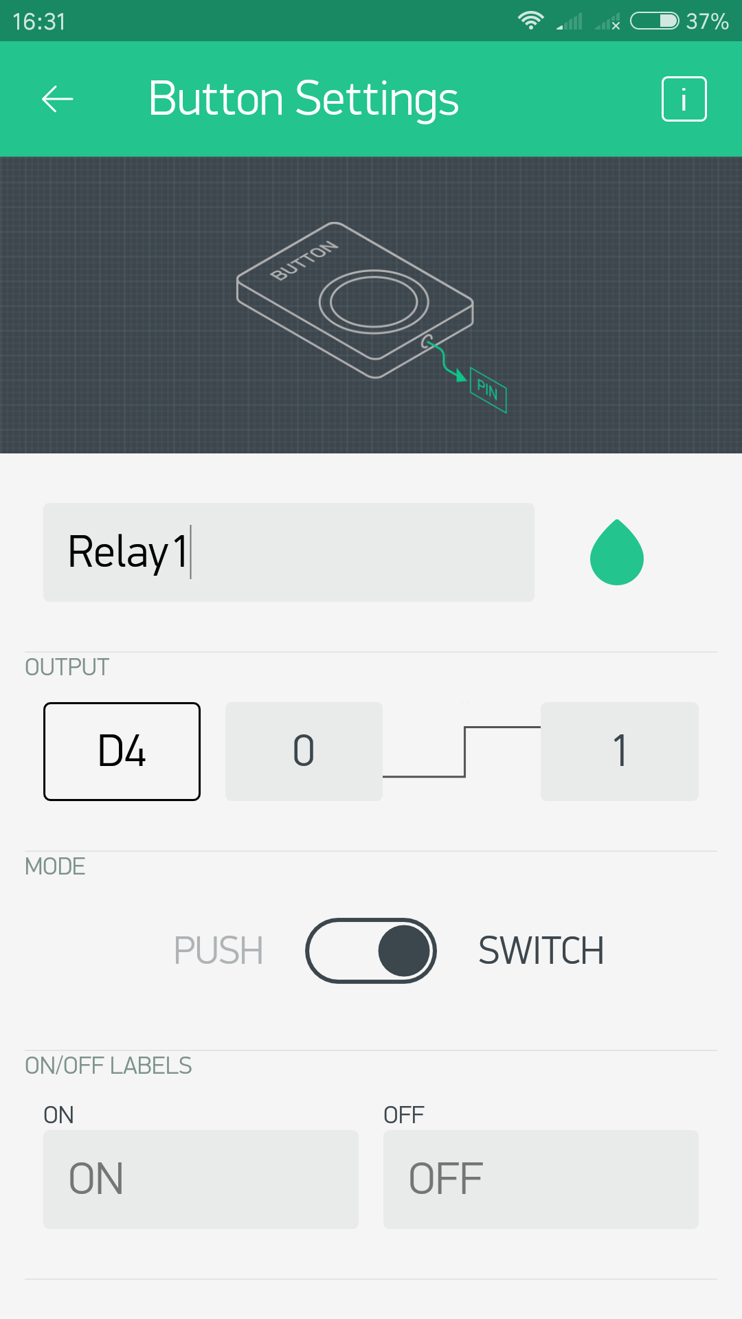
We need to add 2 button wiget here.
Button 1: Name: “Relay 1″; PIN:”D4″; OUTPUT:”0-1″; MODE:”SWITCH”;
Button 2: Name: “Relay 2″; PIN:”D3″; OUTPUT:”0-1″; MODE:”SWITCH”.
LED wigets to indicate the state of the sensors:
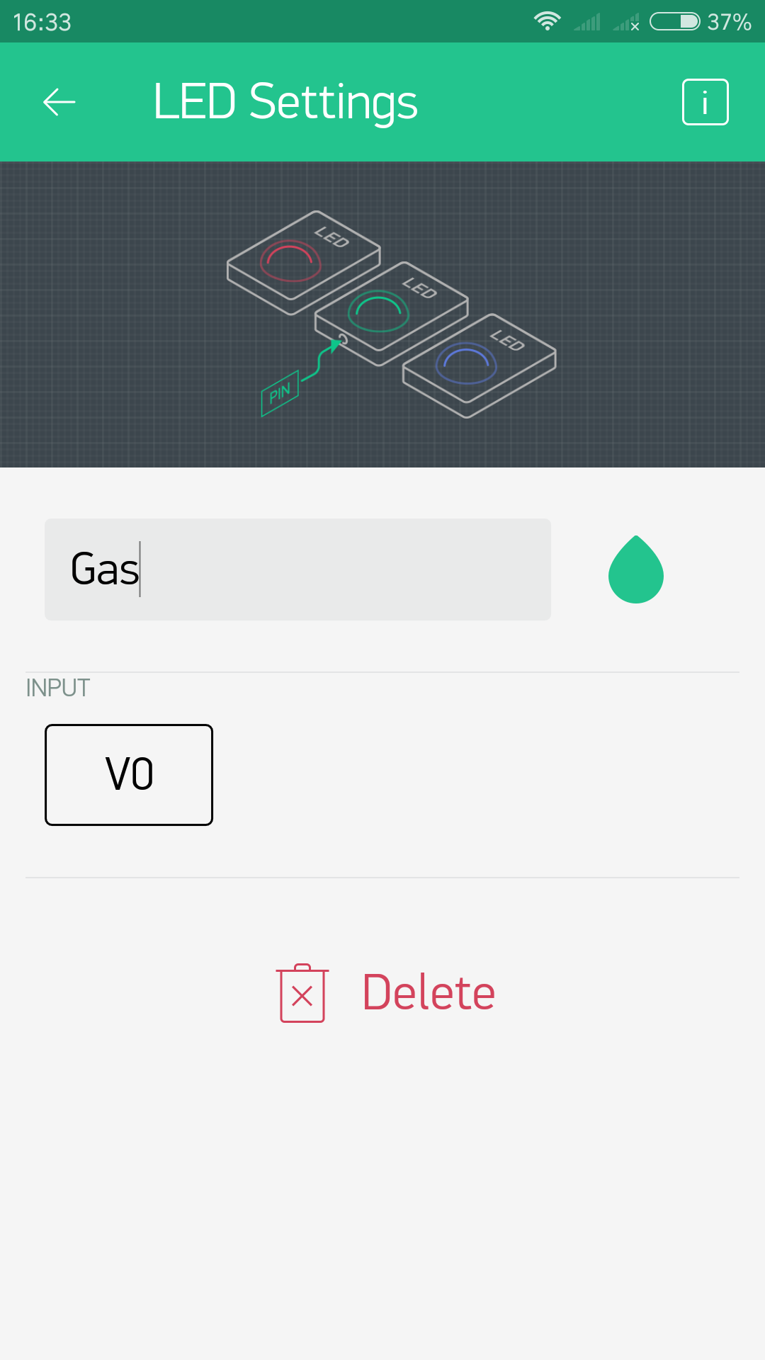
LED 1: Name:”Gas”; INPUT PIN:”V0″;
LED 2: Name:”PIR”; INPUT PIN:”V1″;
LED 3: Name:”FIRE”; INPUT PIN:”V2″.
Slider wiget to control the servo:
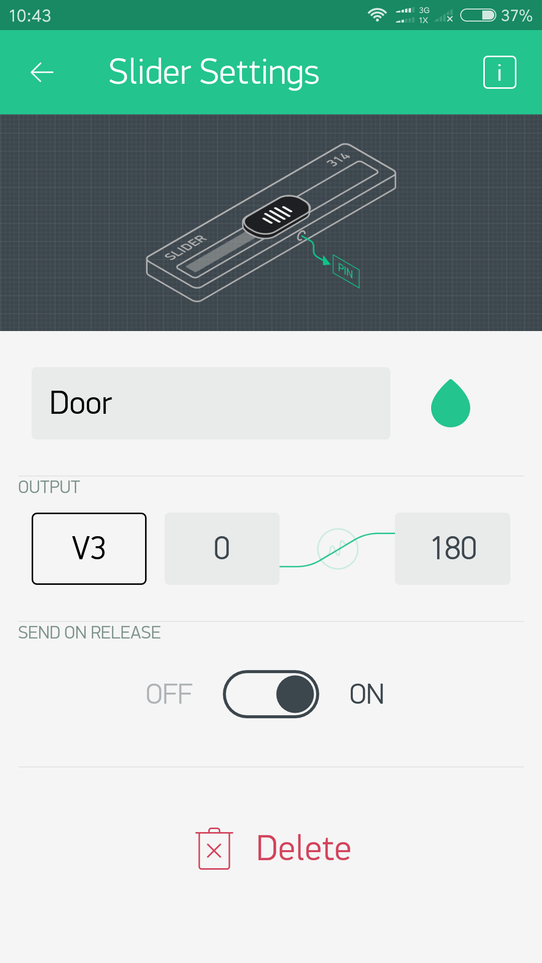
Slider:Name:”Door”; OUTPUT PIN:”V3″;”0~180″;SEND ON RELEASE:”ON”.
Value Display widgets to display the real-time humidity and temperature value:
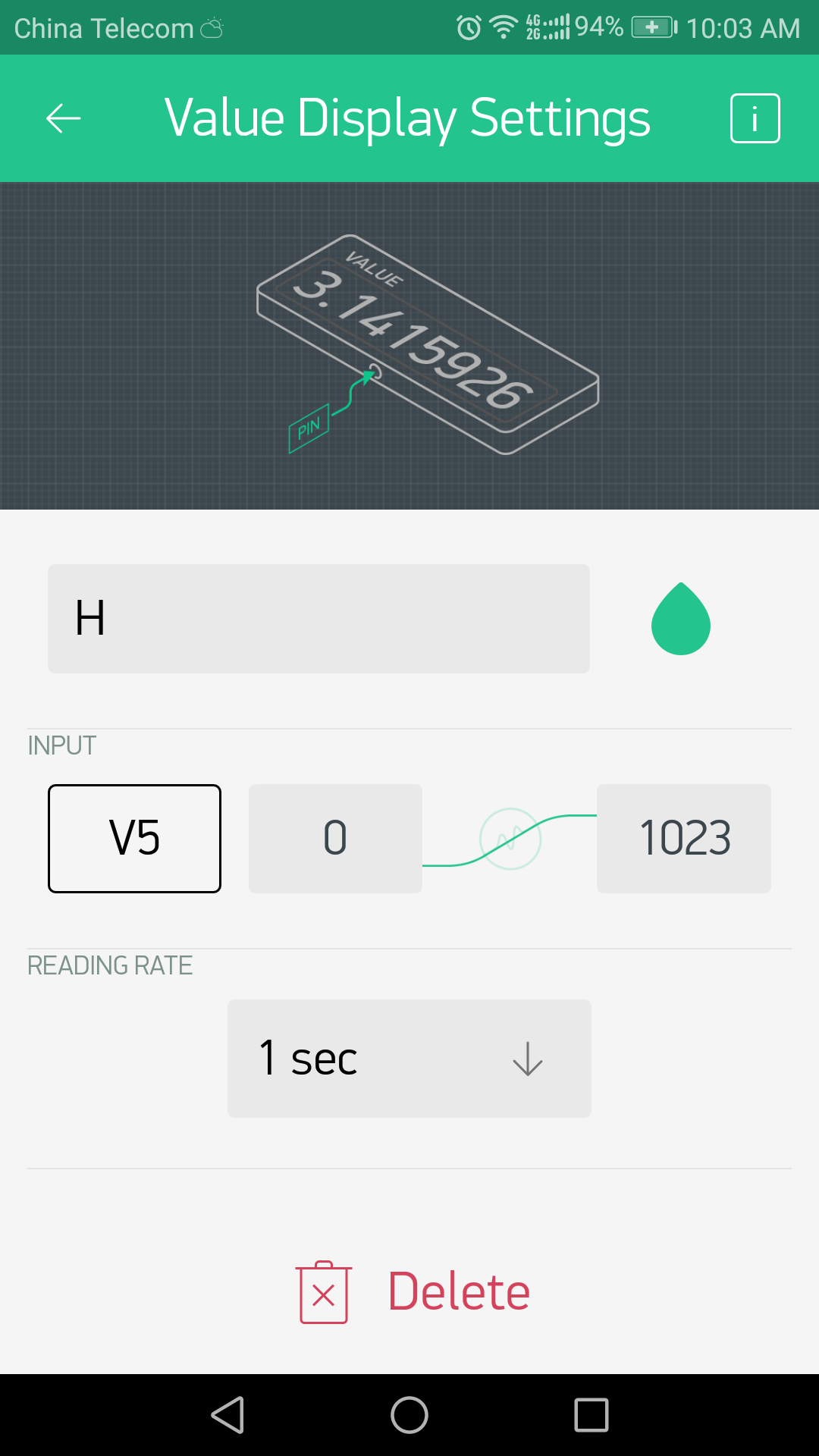
Value Dispaly1:Name:”H”, INPUTPIN:”V5″;”0~1023″;READING RATE:”1sec”;
Value Dispaly1:Name:”T”, INPUTPIN:”V6″;”0~1023″;READING RATE:”1sec”.
zeRGBa wiget to control the RGB module:

zeRGBa:Name:”RGB2″;OUTPUT:”SPLIT”, R PIN:”D11 0~255″,G PIN:”D12 0~255″, B PIN:”D13 0~255″.
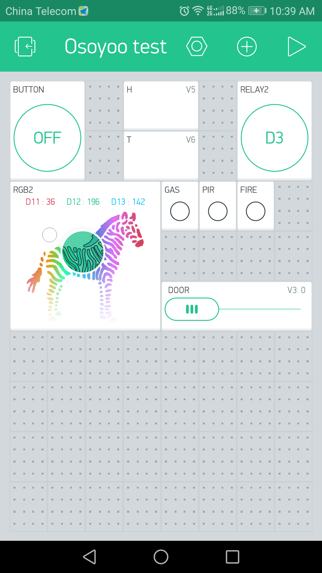
After completed above operations, open the Blynk app and you will see as below:
Code Program
After above operations are completed, make sure that the Yun Shield is on the same network with the computer. Open the Arduino IDE and choose corresponding board type and port type for you project. Then load up the following sketch onto your Arduino.
You can get the Arduino sketch here.
In this example sketch, find this line:
char auth[] =”YourAuthToken”;
This is the Auth Token that you emailed yourself. Please check your email and copy it, then paste it inside the quotation marks.
It should look similar to this:
char auth[] = “f45626c103a94983b469637978b0c78a”;
Find below line and you can also change it, the password “123A456” is used to unlock the door by controlling the servo rotation。
char Master[Password_Length] = “123A456”;
Upload the sketch to the board. Wait until you see something like this:
avrdude done. Thank you.
Congrats! You are all set! Now your hardware is connected to the Blynk Cloud!
Running Result
After you finished all above operations, open the Blynk APP, press the PLAY button. This will switch you from EDIT mode to PLAY mode where you can interact with the hardware. While in PLAY mode, you won’t be able to drag or set up new widgets, press STOP and get back to EDIT mode.
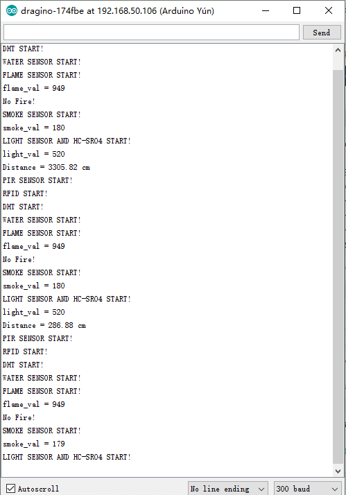
On the other hand, open the serial monitor, and you can see the running state of the entire smart home system as follows:
Now, you can open the door by using the keyboard or by swiping the card through the RFID module, it is also feasible to open the door through a mobile phone, you only need to slide the “Door” slider on the Blynk app.
Enter the correct password. The green light at the door will be lit and the door will be opened.
Enter the wrong password. The red light at the door will be lit and the door will not be opened.
With the corresponding RFID card, you’ll see it as above.The green light at the door will be lit and the door will be opened.
With the wrong RFID card, you’ll see it as above. The red light at the door will be lit and the door will not be opened.
When the flame is approaching, the red light will appear on the door, the buzzer will beep, and the LED wiget representing the flame sensor on the phone app will become a bright state.
When the gas is near the MQ2 gas sensor, the system will also appear as above.
When the ambient light is darkened and the object is near the ultrasonic sensor, the indoor LED will be lit.
When the hand is near the PIR sensor, the LED on the phone representing the sensor will remain bright.

We can easily use the smartphone app to control the relay.
Control RGB color through app.


