


Authorized Online Retailers:
Purchase from US Purchase from Japan


Introduction
In this lesson, we will show how to use the Osoyoo Yun IoT Kit to analog home burglar system.
HARDWARE
- Arduino(Osoyoo Mega2560 here) x 1
- Dragino Yun Shield x 1
- PIR Motion Sensor x 1
- Buzzer Module x 1
- Jumpers
SOFTWARE
Connection
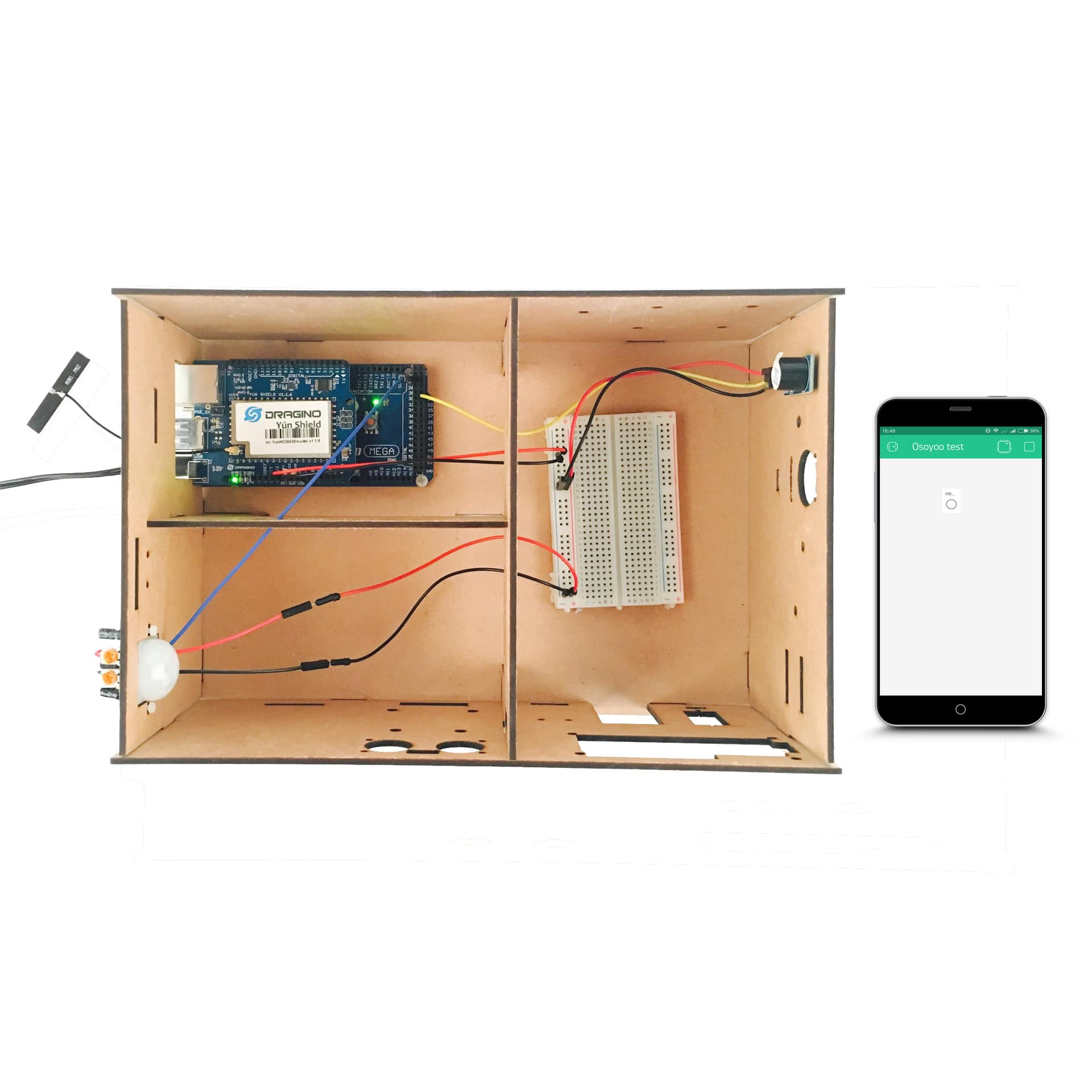
Build the circuit as below:

Here we connect the PIR motion sensor Pin OUT to Arduino digital Pin D24, connect the buzzer I/O Pin to Arduino digital pin D31.
Code Program
After above operations are completed, make sure that the Yun Shield is on the same network with the computer. Open the Arduino IDE and choose corresponding board type and port type for you project. Then load up the following sketch onto your Arduino.
#define BLYNK_PRINT Console
#include "Bridge.h"
#include "Console.h"
#include "BlynkSimpleYun.h"

// You should get Auth Token in the Blynk App.
// Go to the Project Settings (nut icon).
char auth[] = "Your Auth Token";
SimpleTimer timer;
int Buzzer = 31;//the pin of the active buzzer
//PIR_HC_SR501
int pir_hc_sr501 = 24;          // choose the pin for the PIR
int pirState = LOW;             // we start, assuming no motion detected
int pirval = 0;                    // variable for reading the pin status
WidgetLED led2(V1); //register to virtual pin 1

//PIR HC-SR501
void PIRSENSOR () {
    Console.println("PIR SENSOR START!");
    pirval = digitalRead(pir_hc_sr501);  // read input value
    if (pirval == HIGH) {            // check if the input is HIGH
    led2.on(); // set LED on
    digitalWrite(Buzzer, HIGH);
    if (pirState == LOW) {
    // we have just turned on
    Console.println("Motion detected!");
    // We only want to print on the output change, not state
    pirState = HIGH;
    }
  }
  else
  {
    led2.off();  //set LED off
    if (pirState == HIGH){
    // we have just turned of
    digitalWrite(Buzzer, LOW);
    Console.println("Motion ended!");
    // We only want to print on the output change, not state
    pirState = LOW;
    }
  }
}

void setup()
{
  Blynk.begin(auth);
  Bridge.begin();
  Console.begin();
  pinMode(Buzzer, OUTPUT);      // declare Buzzer as output
  pinMode(pir_hc_sr501, INPUT);     // declare sensor as input
  timer.setInterval(1000, PIRSENSOR);
  while (!Console);{}
}
void loop() {
  // this is where the "polling" occurs
  timer.run();
  Blynk.run();
}
Add a Widget
Overhere we need to add an LED wiget. Follow the next operations:
Tap anywhere on the canvas to open the widget box. All the available widgets are located here. Now pick an LED.
Widget Box

Drag-n-Drop – Tap and hold the Widget to drag it to the new position.
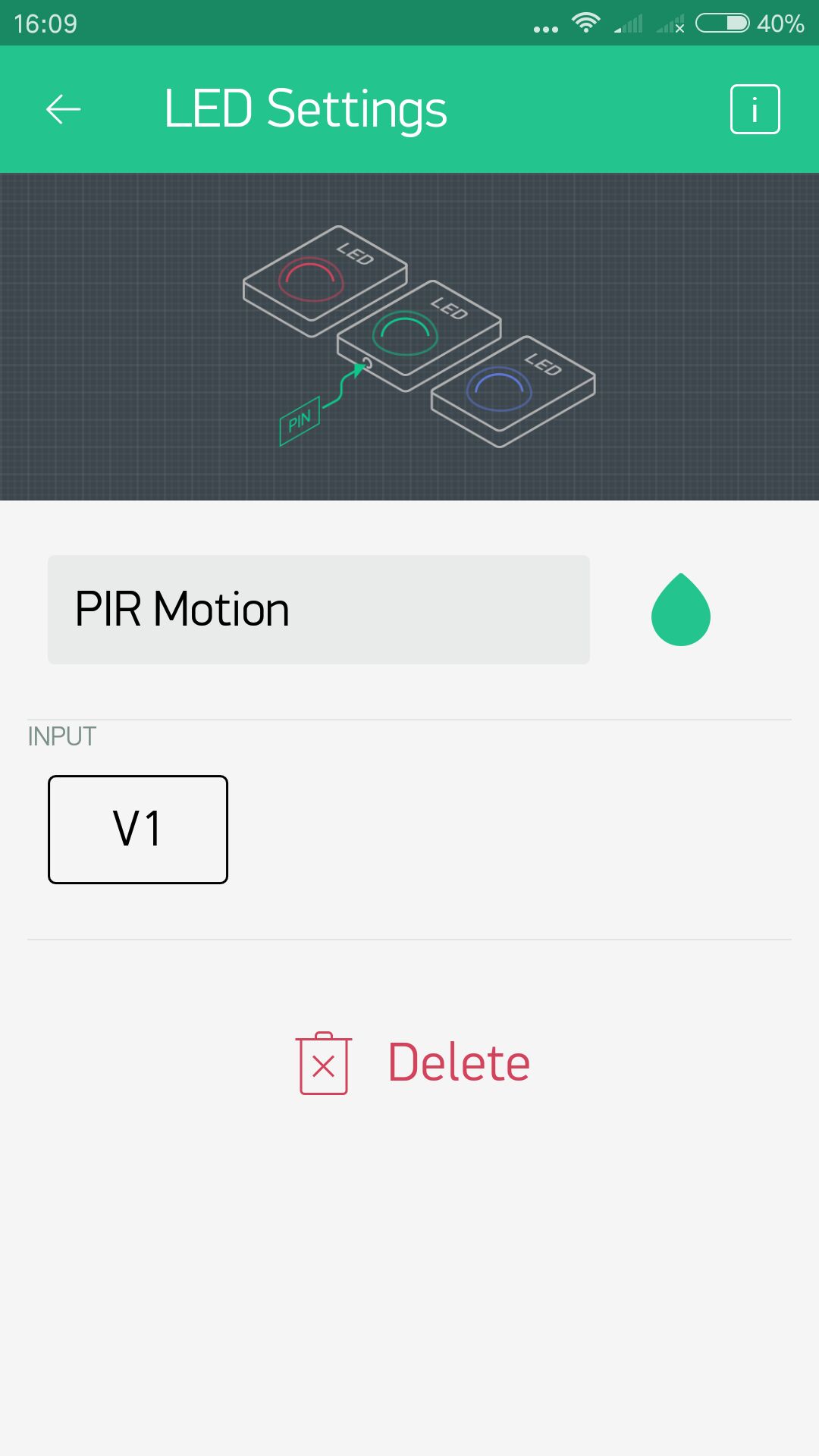
Widget Settings – Each Widget has it’s own settings. Tap on the widget to get to them. The most important parameter to set is PIN. Connect the LED wiget to V1.
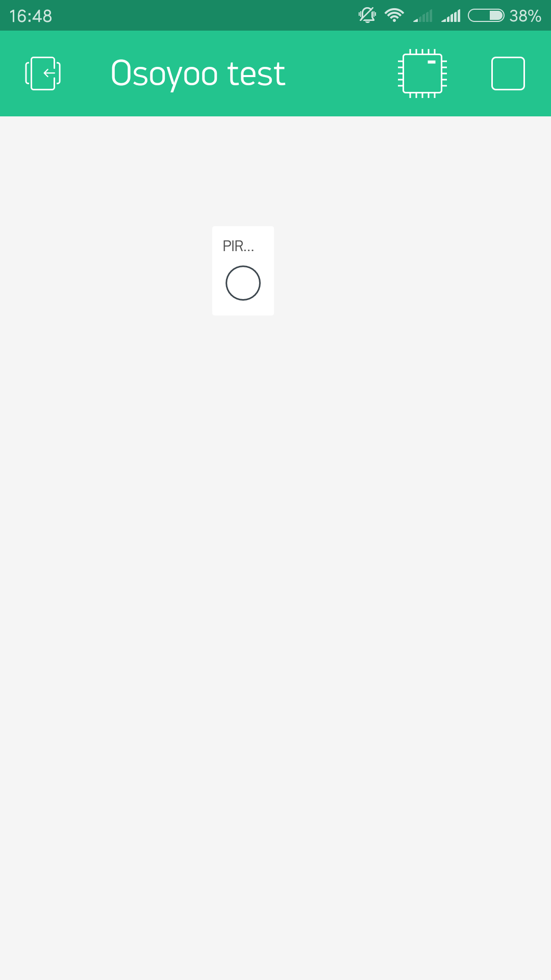
Running Result
After you finished all above operations, open the Serial Monitor, then open the Blynk APP, press the PLAY button. This will switch you from EDIT mode to PLAY mode where you can interact with the hardware. While in PLAY mode, you won’t be able to drag or set up new widgets, press STOP and get back to EDIT mode.
When you use one hand close to the PIR motion sensor,the buzzer will be activated and the LED on the phone will be lit.
Now you’ve learned how to make a simple family burglar system through this experiment, and it can also be used as a home lighting control system.


