Note: ALL OSOYOO Products for Arduino are Third Party Board which is fully compatitable with Arduino
Introduction

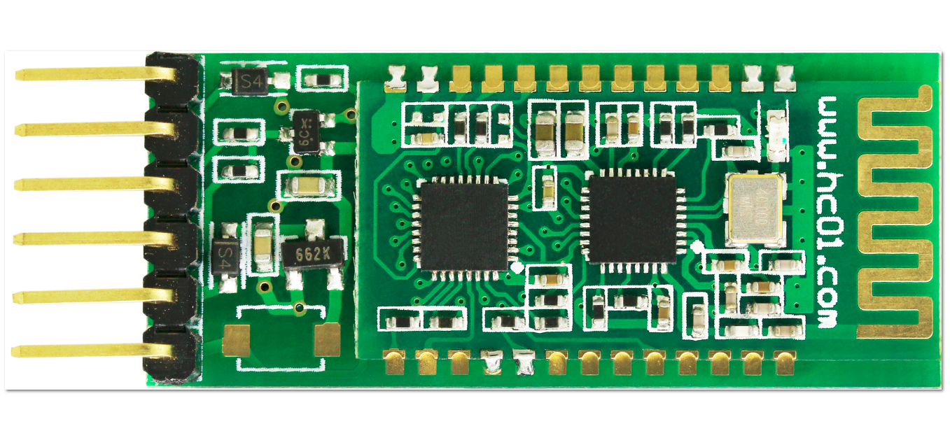
HC-02 Bluetooth serial communication module is based on the Bluetooth V2.0 Bluetooth protocol data transmission module, high stability, ultra low power consumption, industrial grade Bluetooth data transmission module.
Users do not need to care about complex wireless communication configuration and transmission algorithms. They only need to connect to devices through TTL serial port. Powered the HC-02 slave module, and can be connected to the mobile phone for data transmission. In addition, it can be used with HC-05 or HC-06 hosts (matching code, default is 1234) to connect, can replace a traditional serial line, save wiring work. It’s very flexible.
If you need to use iphone or ipad to control your project, hc-02 4.0 ble slave module with 6pin baseboard may be a good choice.Fully compatible with ios7.0 or later.Also compatible with Android 4.3 or later.
In this lesson, we will show what is HC-02 bluetooth module and how to setup communications between an your board and a Bluetooth device running serial terminal software – in this case an Android/iOS smartphone. Please note that the Bluetooth module used in this tutorial is not compatible with iOS devices.
Please note:
- If the version of the Android os is less than 4.3. it is not compatible.
- This module supports bluetooth 4.0 ble mode and bluetooth 2.0 mode.
- If you are not so familiar with the Bluetooth, you can get more info about blutooth from here.
Features
| Model |
HC-02 |
Module size |
27*13mm |
| Work band |
2.4G |
Air rate |
2Mbps |
| Communication interface |
UART3.3V TTL |
Antenna interface |
built-in PCB antenna |
| Working voltage |
3.0~3.6V |
Communication current |
30mA |
| Baud rate |
1200~115200bps |
Receiver sensitivity |
-85dBm@2Mbps |
| Communication level |
3.3V |
Working humidity |
10%~90% |
| The transmitting power |
6dBm (maximum) |
Storage temperature |
-40 C ~+85 C |
| Reference distance |
10m |
Working temperatur |
-25 C ~75 C |
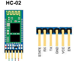
- Core module uses HC-02, leads from the module interface includes VCC, GND, TXD, RXD, LED status output pin.
- Led indicate Bluetooth connection status, flashing Bluetooth connectivity, lit the Bluetooth connection and open a port Backplane
- 3.3V LDO input voltage 3.6 6V, the input voltage to prohibit more than 7V
- The interface level 3.3V, can be directly connected the various SCM (51, AVR, PIC, ARM, MSP430, etc.), the 5V MCU also can be connected directly.
- Open to the effective distance of 10 meters, over 10 meters is also possible, but not of this the quality of the connection of the distance do to ensure.
- After the pair when full-duplex serial port to use, do not need to know anything about the Bluetooth protocol, but only supports 8 data bits, 1 stop bit, no parity communication format, which is the most commonly used communication format does not support other formats .
- Compact (3.57cm * 1.52cm), the factory chip production to ensure the placement quality. And sets of transparent heat shrink tubing, dust and beautiful, and anti-static.
Pin Configuration
| Pin Number |
Pin Name |
Description |
| 1 |
Enable / Key |
This pin is used to toggle between Data Mode (set low) and AT command mode (set high). By default it is in Data mode |
| 2 |
Vcc |
Powers the module. Connect to +5V/+3.3V Supply voltage |
| 3 |
Ground |
Ground pin of module, connect to system ground. |
| 4 |
TX – Transmitter |
Transmits Serial Data. Everything received via Bluetooth will be given out by this pin as serial data. |
| 5 |
RX – Receiver |
Receive Serial Data. Every serial data given to this pin will be broadcasted via Bluetooth |
| 6 |
State |
The state pin is connected to on board LED, it can be used as a feedback to check if Bluetooth is working properly. |
| 7 |
LED |
Indicates the status of Module
- Blink once in 2 sec: Module has entered Command Mode
- Repeated Blinking: Waiting for connection in Data Mode
- Blink twice in 1 sec: Connection successful in Data Mode
|
Schematics
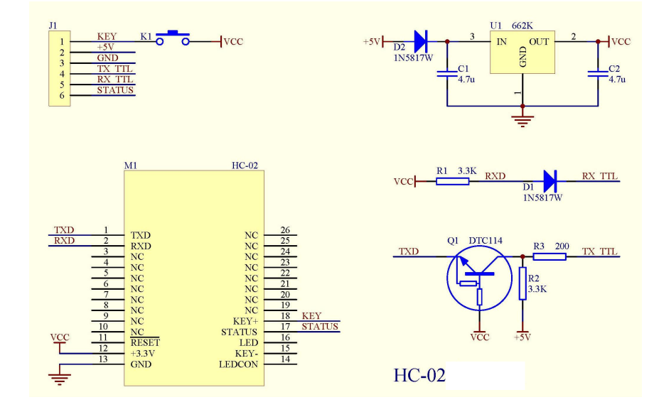
More info about the HC-02 BLE module please check this link.
Preparation
HARDWARE
- Osoyoo Basic Board (Fully compatible with Arduino UNO rev.3) x 1
- HC-02 Bluetooth Module x 1
- Android smartphone x 1
- iPhone(ios7.0 or later) x 1
- Jumpers
- USB Cable x 1
- PC x 1
SOFTWARE
- IDE (version 1.6.4+)
- library: SoftwareSerial.h
- Bluetooth Terminal HC-05 APP for Android
- Bluetooth Terminal app for iOS
Example
In this example, we will show how to use an smart phone to control the board on-board LED via bluetooth protocol.
Connection
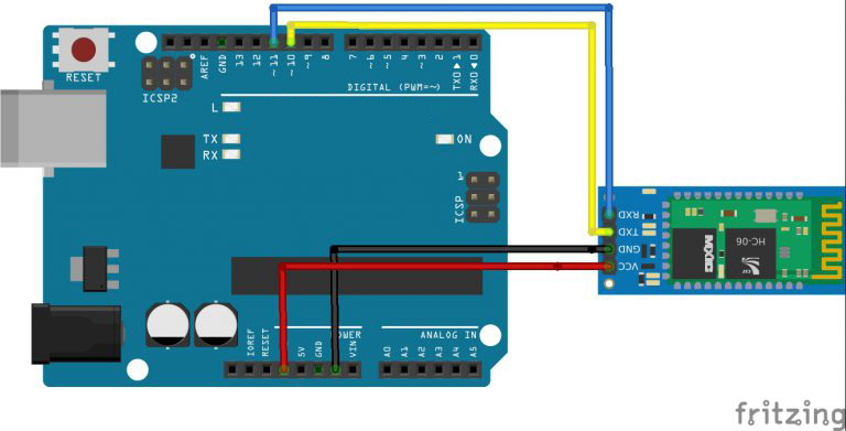
| Osoyoo Basic board |
HC-02 |
| 3.3V |
VCC |
| GND |
GND |
| D10/Software RX |
TXD |
| D11/Software TX |
RXD |
Overhere we use the Software serial port of the board, connect them as below fritzing:
Code Program
After above operations are completed, connect the board to your computer using the USB cable. The green power LED (labelled PWR) should go on.Open the IDE and choose corresponding board type and port type for you project. Then download and unzip the sketch file from https://osoyoo.com/driver/v2.1car/hc02-test.zip , then upload onto your board.
Here are the code details:
#include "SoftwareSerial.h"// import the serial library

SoftwareSerial mySerial(10, 11); // RX, TX
int ledpin=13; // led on D13 will be turn on / off as per APP input
int BluetoothData; // the data given from Computer

void setup()
{
   Serial.begin(9600);
  Serial.println("Input letter a or b to turn on/off on board LED in D13!");
  // put your setup code here, to run once:
  mySerial.begin(9600);
  Serial.println("please send letter 1 or 0 from HC-05 APP to turn on/off LED ..");
  pinMode(ledpin,OUTPUT);
}

void loop()
{
  // put your main code here, to run repeatedly:
  if (mySerial.available())
  {
    BluetoothData=mySerial.read();
    if(BluetoothData=='1')
    {
      // if letter 1 is sent from APP   ....
      digitalWrite(ledpin,1);
     Serial.println("LED  On D13 ON ! ");
    }
    if (BluetoothData=='0')
    {
      // if Letter 0 is sent from APP ....
      digitalWrite(ledpin,0);
      Serial.println("LED  On D13 Off ! ");
    }
  }
delay(100);// prepare for next data ...
}
For Android Smart Phone User
In Google Play, please search Bluetooth Terminal HC-05, you will find a blue color APP , install this APP into your Android Phone.
Open your cell phone Setting, pair a Bluetooth device called HC-02 , input passcode 1234 to add this device to your cell phone.
Now open Bluetooth Terminal HC-05 APP, select the HC-02 device from paired device list.
You will see following user interface page:
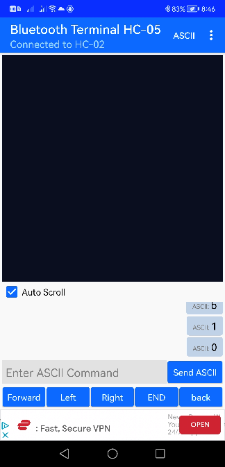
You can input a letter “a” in the text field and click Send ASCII button, a letter “a” will be sent to bluetooth module and LED in D13 will turn on.
You can input a letter “b” in the text field and click Send ASCII button, a letter “a” will be sent to bluetooth module and LED in D13 will turn off.
For iPhone User
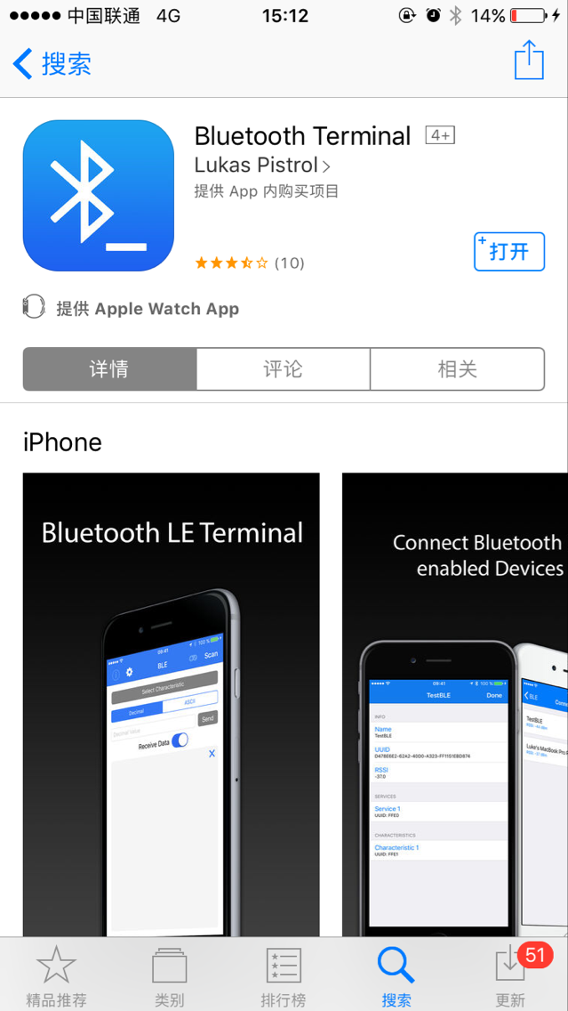
Download the Bluetooth Terminal app from the APP Store.
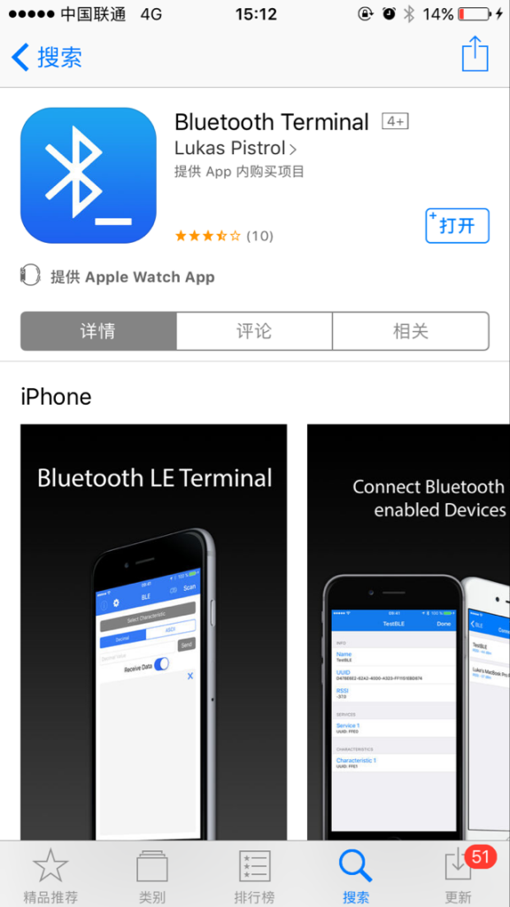
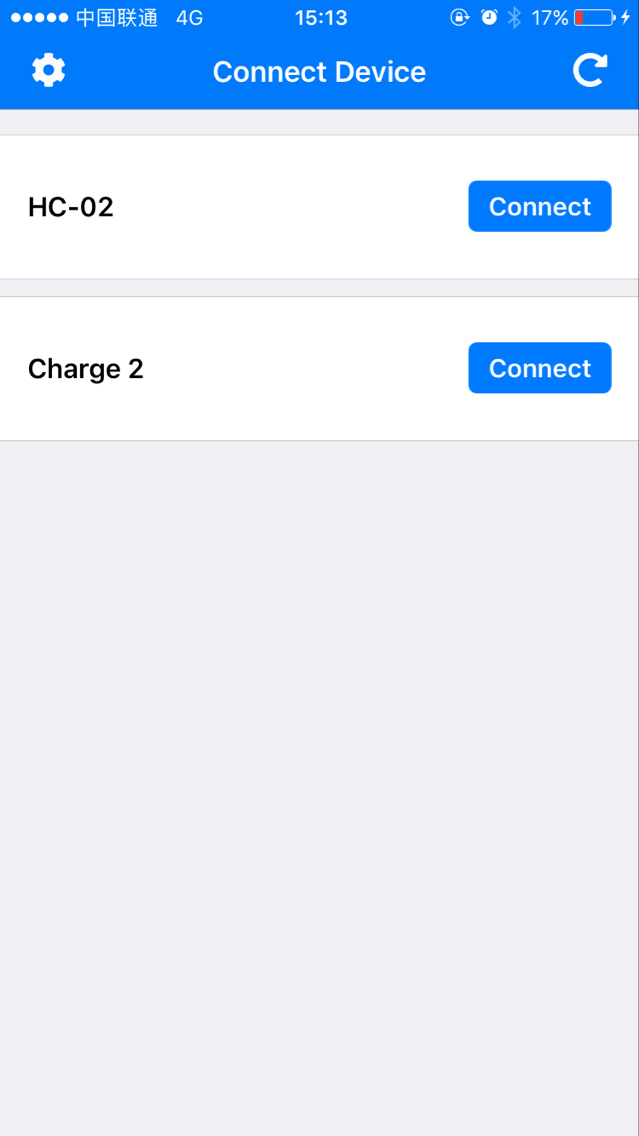
After the above operation is completed, open the Bluetooth Terminal, and you will see the bluetooth list as below:

Choose “HC-02”, then click the connect button.
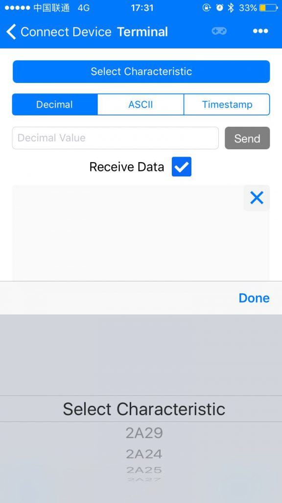
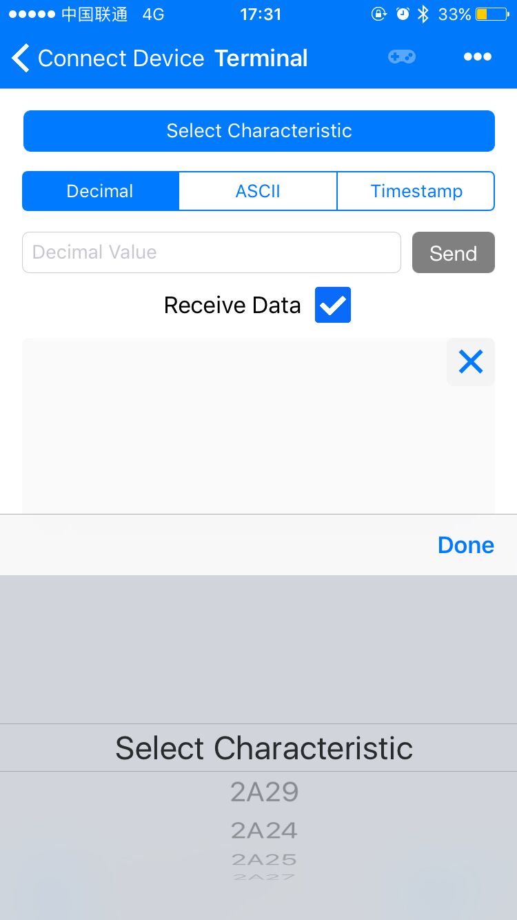
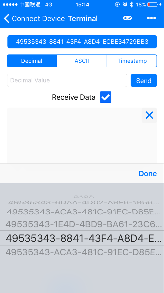
In this step, click “Select Characteristic”, you will see a scroll bar below the button, select entries with the beginning of “49535343-8841-43F4-A8D4” for your HC-02 BLE module.

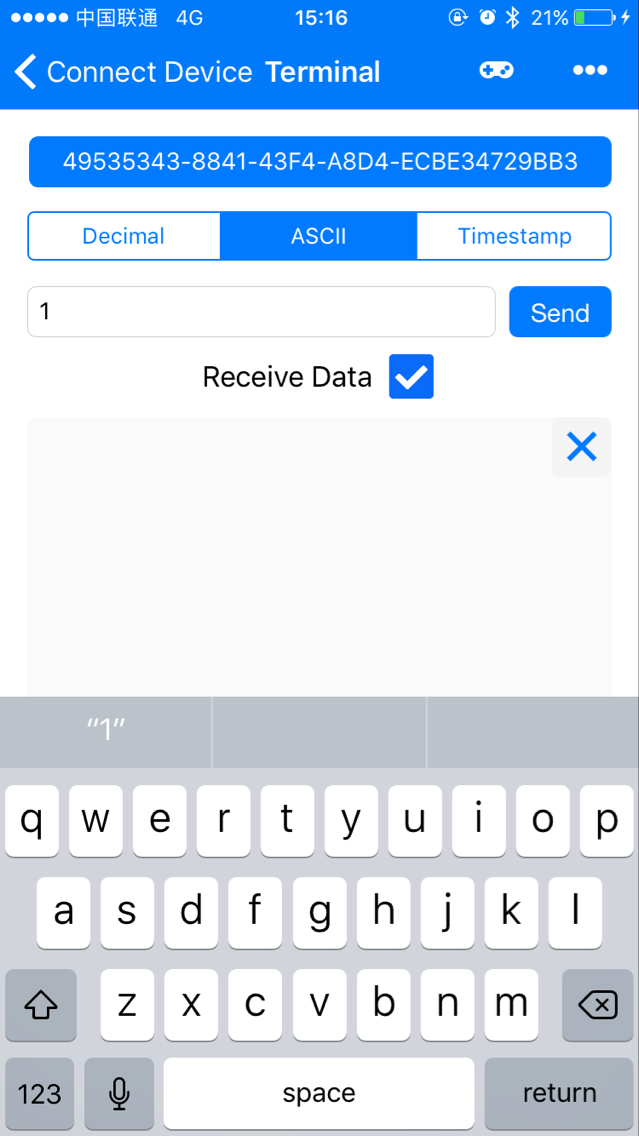
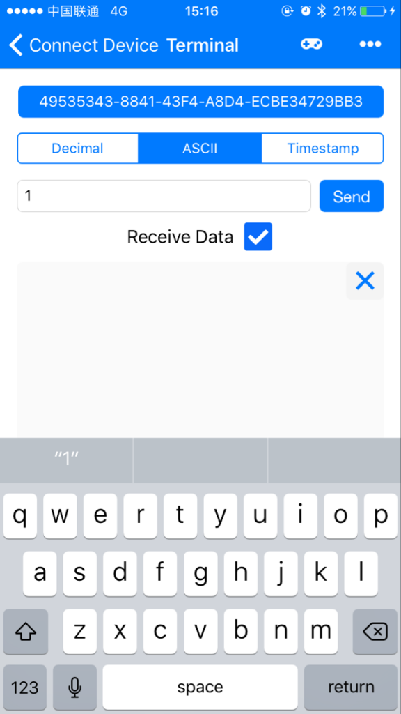
Choose “ASCII”, and you can enter your command here, just press the “Send” button to send your command to the board via bluetooth.
Same as Android APP, you can send a character “1” to bluetooth module and turn on LED in D13 , or send a character 0 to turn off LED.
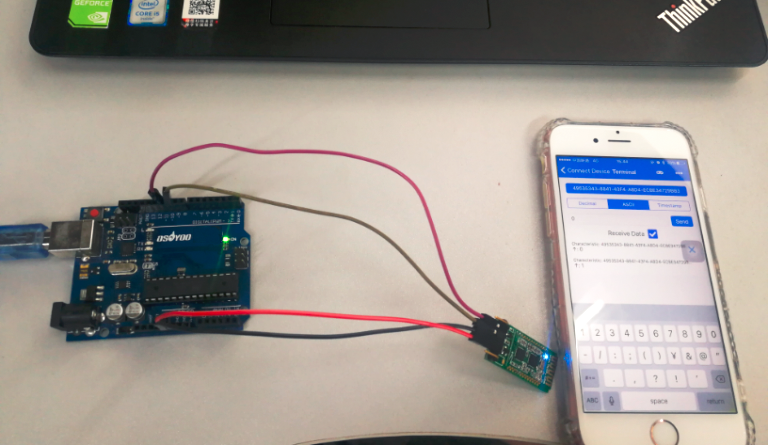
Running Result
A few seconds after the upload finishes, open the Bluetooth Terminal HC-05 app and connect your Android phone with the HC-02 module, simply send “1” or “0” to turn on / off LED.
At the same time, open your Arduino Serial Monitor (see following picture)
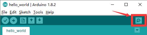
you will see following result.
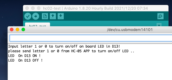
Note: you must choose the correct Baud rate 9600 in Arduino Serial monitor for your serial monitor, be careful!!!