Introduction
In Experiment Reading a Potentiometer, you got to use a potentiometer, which varies resistance based on the twisting of a knob and, in turn, changes the voltage being read by the analog input pin. In this circuit you’ll be using a photoresistor, which changes resistance based on how much light the sensor receives. You will read the light value of the room and have an LED turn on if it is dark and turn off if it is bright. That’s right; you are going to build a night light!
Parts Needed
You will need the following parts:
- 1x micro:bit
- 1x Micro B USB Cable
- 1x micro:bit Breakout (with Headers)
- 1x Breadboard
- 8x Jumper Wires
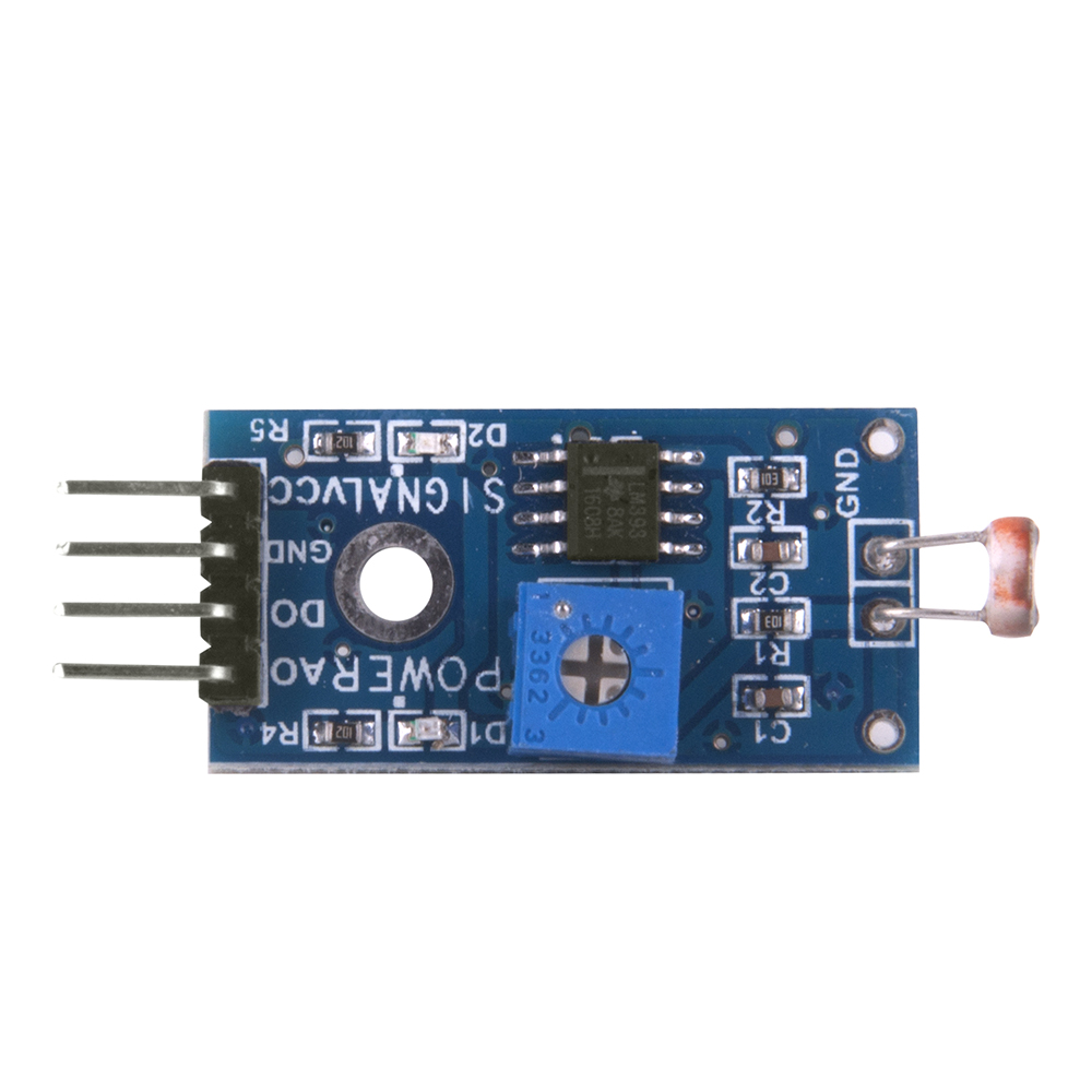
- 1x Photoresistor Module
- 1x LED Module
About Photoresistor
Photocells are sensors that allow you to detect light. They are small, inexpensive, low-power, easy to use and don’t wear out. For that reason they often appear in toys, gadgets and appliances. They are often referred to as CdS cells (they are made of Cadmium-Sulfide), light-dependent resistors (LDR), and photoresistors.
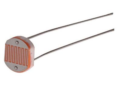
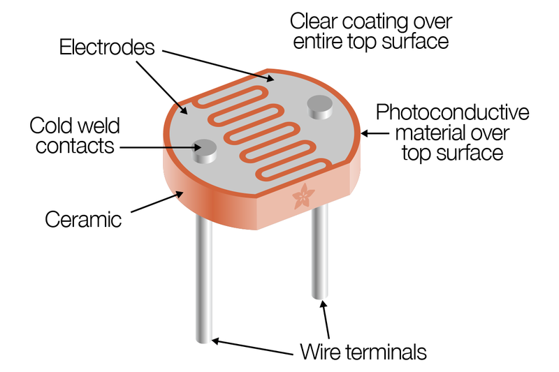
Photocells are basically a resistor that changes its resistive value (in ohms Ω) depending on how much light is shining onto the squiggly face.When it is dark, the resistance of a photoresistor may be as high as a few MΩ. When it is light, however, the resistance of a photoresistor may be as low as a few hundred ohms. They are very low cost, easy to get in many sizes and specifications, but are very innacurate. Each photocell sensor will act a little differently than the other, even if they are from the same batch. The variations can be really large, 50% or higher! For this reason, they shouldn’t be used to try to determine precise light levels in lux or millicandela. Instead, you can expect to only be able to determine basic light changes.
This graph indicates approximately the resistance of the sensor at different light levels:
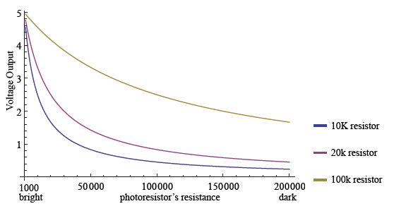
Note: We use the photoresistor module in this project.
Hardware Hookup
Ready to start hooking everything up? Check out the wiring diagram below to see how everything is connected.
| Polarized Components |
Pay special attention to the component’s markings indicating how to place it on the breadboard. Polarized components can only be connected to a circuit in one direction. |
Wiring Diagram for the Experiment
| LED Module |
Micro Bit Breakout |
| GND |
GND |
| VCC |
3.3V |
| OUT |
P16 |
| Photoresistor Module |
Micro Bit Breakout |
| GND |
GND |
| VCC |
3.3V |
| A0 |
P0 |
Note: The full sized breadboard power rails have a break down the middle. If you end up using the lower half of the power rail you will need to jump between the upper end and lower end.
Running Your Script
Either copy and paste, or re-create the following code into your own MakeCode editor by clicking the open icon in the upper right-hand corner of the editor. You can also just download this example by clicking the download button in the lower right-hand corner of the code window.
Note: You may need to disable your ad/pop-up blocker to interact with the MakeCode programming environment and simulated circuit!
Code to Note
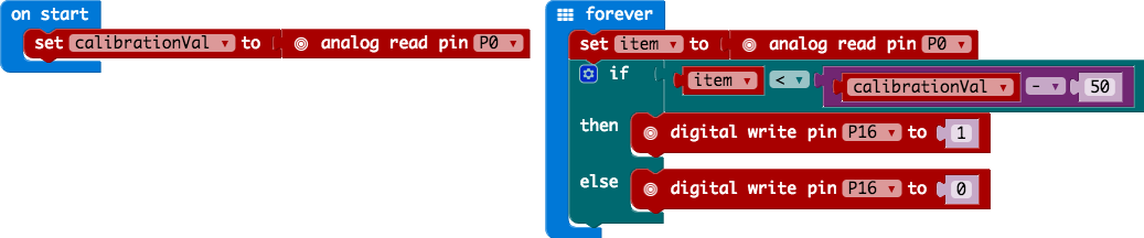
Let’s take a look at the code blocks in this experiment.
If you are having a hard time viewing this code, click on the image above to get a better look!
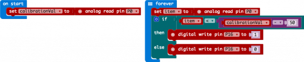
On Start
In previous experiments you have only used the forever block, which loops your code forever. The On start block is a block of code that only runs once at the very beginning of your program. In this program we use it to set a calibration value once, and then compare the changing value in the forever loop. This is a great spot for code that you only want to run a single time.
calibrationVal is a calibration variable. Your micro:bit takes a single reading of the light sensor in the on start block of code and uses this value to compare against the calibrationVal variable in the forever loop. This value doesn’t change in the forever block, as it is set in the on start block. To update this value you can press the RESET button on the back of your micro:bit or power cycle the board.
If/Else
If the light value variable that is constantly being updated in the forever block is less than the calibration value minus 50, it is dark and the LED should turn on. The (-50) portion of the if block is a sensitivity value. The higher the value, the less sensitive the circuit will be; the lower the value, the more sensitive it will be to lighting conditions.
The if block is a logical structure. If the logical statement that is attached to it (item < calibrationVal -50) is true, then it will execute the code blocks inside of the if. If that statement is false, it will execute the else blocks. In this case if the statement is true (the room is dark), then the micro:bit will turn on the LED on pin 16; else (if the room is bright), it will turn the LED off using a digital write block.
Note: The logical operator blocks and the math block used to build the logical statement. You can find them under the Logic and Math blocks respectively.
What You Should See
When the micro:bit runs the program it will take a single reading from the light sensor and use that as a calibration value of the “normal” state of the room. When you place your hand over the light sensor or turn the lights off, the LED will turn on. If you turn the lights back on or uncover the light sensor, the LED will turn off.
Troubleshooting
LED Remains Dark
You may have been leaning over the light sensor when the code started. Make sure the light sensor is reading the normal light in the room at startup. Try resetting the micro:bit.
Still Not Quite Working
Double-check your wiring of the signal pin; sometimes you miss a breadboard connection by a row.