Note: ALL OSOYOO Products for Arduino are Third Party Board which is fully compatitable with Arduino
Content
- Introduction
- Preparations
- What is IR?
- Examples
Introduction
IR, or infrared, communication is a common, inexpensive, and easy to use wireless communication technology. IR light is very similar to visible light, except that it has a slightlty longer wavelength. This means IR is undetectable to the human eye – perfect for wireless communication. In this lesson, we will show how to use the Infrared Transmitting Module and Infrared Receiving Module with the Osoyoo basic board.
Preparations
Hardware
- Osoyoo Basic Board (Fully compatible with Arduino UNO rev.3) x 1
- Infrared Transmitting Module x 1
- Infrared Receiving Module x 1
- Breadboard x 1
- Jumpers
- USB Cable x 1
- PC x 1
Software
- IDE (version 1.6.4+)
- IRremote.h
What is IR?
Infra-Red light is actually normal light with a particular colour. We humans can’t see this colour because its wave length of about 950nm is below the visible spectrum. That’s one of the reasons why IR is chosen for remote control purposes, we want to use it but we’re not interested in seeing it. Another reason is because IR LEDs are quite easy to make, and therefore can be very cheap, thus making it ideal for us hobbyists to use IR control for our own projects. We need to konw there are many more sources of Infra-Red light. The sun is the brightest source of all, but there are many others, like: light bulbs, candles, central heating system, and even our body radiates Infra-Red light. A common modulation scheme for IR communication is something called 38kHz modulation. There are very few natural sources that have the regularity of a 38kHz signal, so an IR transmitter sending data at that frequency would stand out among the ambient IR. 38kHz modulated IR data is the most common, but other frequencies can be used. When you hit a key on your remote, the transmitting IR LED will blink very quickly for a fraction of a second, transmitting encoded data to your appliance. 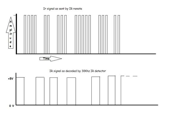
If you were to hook an oscilloscope up to your TV remote’s IR LED, you would see a signal similar to the one above. This modulated signal is exactly what the receiving system sees. However, the point of the receiving device is to demodulate the signal and output a binary waveform that can be read by a microcontroller. When you read the OUT pin of the VS1838B with the wave from above, you will see something like the second.
Modulation
As everything that radiates heat, also radiates Infra-Red light. Therefore we have to take some precautions to guarantee that our IR message gets across to the receiver without errors.Modulation of the signal on a carrier frequency is the answer to make our signal stand out above the noise. With modulation we make the IR light source blink in a particular frequency. The IR receiver will be tuned to that frequency, so it can ignore everything else. In the picture below you can see a modulated signal driving the IR LED of the transmitter on the left side. The detected signal is coming out of the receiver at the other side. 
(Thanks to SBProjects.com for the gif and excellent IR resource!)
Technical Details of VS1838B IR Receiver
- Model Number : VS1838B;
- Working Voltage :2.7V to 5.5V
- Reception Distance : 18M;
- Reception Angle : ± 45 Degree;
- Low Level Voltage : 0.4V
- High Level Voltage : 4.5V;
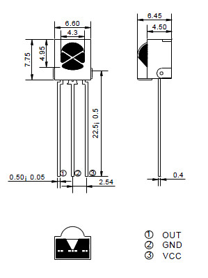
- Body Size : 7 x 7 x 5mm / 0.27″ x 0.27″ x 0.2″(L*W*T);
- Pin Length : 22.5mm / 0.88″
- Pitch : 2mm / 0.08″;
The pinout for VS1838B IR Receiver:
Infrared Transmitting Module
This tiny unit allows users to connect to any microcontroller that operates at 5v logic level. Using an IR transmitter module you can send signals, commands or queries from this module. Commonly used for tv remote control from a distance of 5 feet or more. For robotic usage you need the IR receiver on the other end
. 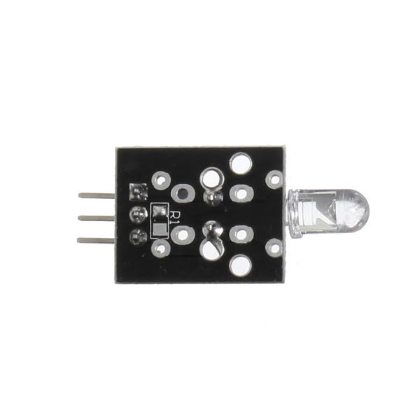
Holding the board with the pins facing towards you, the left labelled – is for ground, the middle pin is for 5v power supply and the right most pin labelled S is for digital pin 11. IR Transmitter Module Keyes KY-005, emits infrared light at 38kHz.
Specifications
- Dimensions: 35 x 15 x 5 mm (L x W x H)
- Operating Voltage: 5VDC
- Current Draw: 30-60mA
- Pulse Forward Current: 0.3 – 1A
- Power Dissipation: 90mW
- Operating Temperature: -25 ~ 80 ℃
IR-REMOTE LIBRARY:
Note: The following library must be installed in your installation for this to work!
CLICK HERE – IR REMOTE CONTROL: ARgithub.com/shirriff/IRremoteDUINO LIBRARY NOTE!! If you have a late version of IDE with a library IRRobotRemote, it may conflict and you may have to remove that library. Make sure to delete the path of Arduino(root)/libraries/RobotIRremote. Where the folder of Arduino(root) refers to the install directory of Arduino. The library Robot IRremote has similar definitions to IRremote and causes errors.
Examples
Read codes from IR Remote
This example will show you how to read IR remote codes from any IR remote using the VS1838B IR receiver and an controlled board. Once you can receive codes from individual button presses, your remote control and basic board become a general purpose, short range, communication interface! The first thing you need to do is make sure the IR library has been installed, Instructions on how to install an library can be found here.
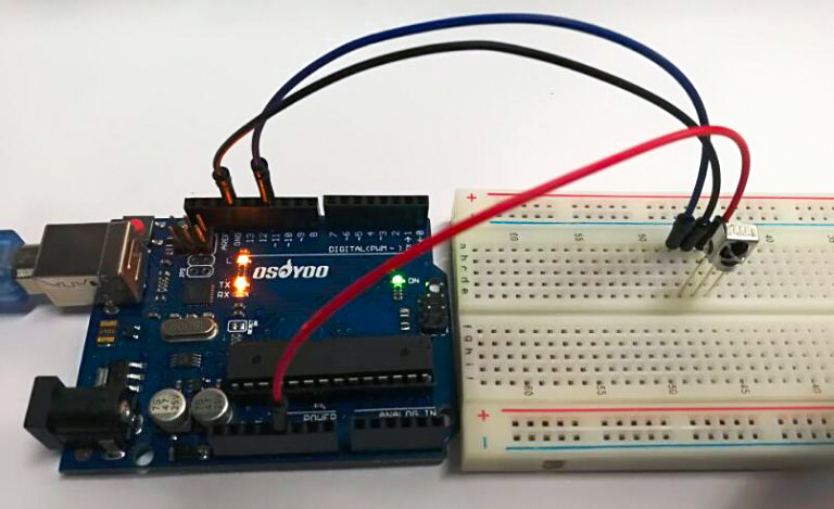
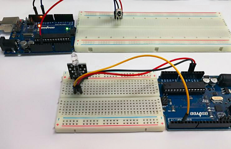
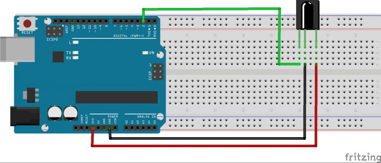
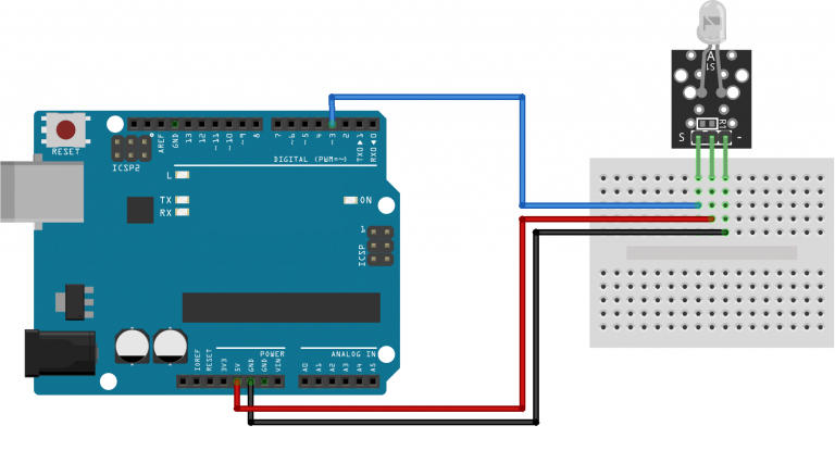
Connection
Build the circuit as below:
Code Program
After above operations are completed, connect the board to your computer using the USB cable. The green power LED (labelled PWR) should go on.Open the IDE and choose corresponding board type and port type for you project. Then load up the following sketch onto your board.
#include <IRremote.h>  // use the IRRemote.h
const int irReceiverPin = 2;  //the SIG of receiver module attach to pin2
IRrecv irrecv(irReceiverPin); //Creates a variable of type IRrecv
decode_results results;    // define resultsas

void setup()
{
  Serial.begin(9600);    //initialize serial,baudrate is 9600
  irrecv.enableIRIn();   // enable ir receiver module
}

void loop()
{
  if (irrecv.decode(&results)) //if the ir receiver module receiver data
  {
    Serial.print("irCode: ");    //print "irCode: "
    Serial.print(results.value, HEX); //print the value in hexdecimal
    Serial.print(",  bits: ");  //print" , bits: "
    Serial.println(results.bits); //print the bits
    irrecv.resume();    // Receive the next value
  }
  delay(600); //delay 600ms
}
When specific buttons are pressed, you can use the incoming values to do something else in your code, for example turn on and off a motor or LED. The results from each button press can be found by calling the value() method:
results.value
You can print the values to the Serial Monitor window:
Serial.println(results.value, HEX); //prints the hex value a a button press
Running Result
The sketch will automatically decode the type of remote you are using and identify which button on your remote is pressed. Open the Serial Monitor in the IDE at 9600 bps and hit different buttons on your remote.
Transmitting infrared signals
In this example, I will show you how to use the Osoyoo basic board with the ky005 module.
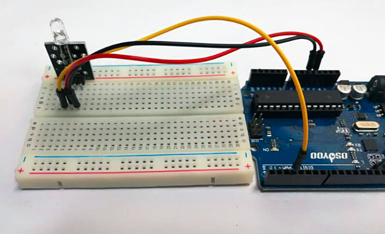
Connect the Power line (middle) and ground (-) to +5 and GND respectively. Connect signal (S) to pin 3 on the board or pin 9 on Mega. The pin number for the infrared transmitter is determined by the IRremote library, check the download section below for more info.
| KY-005 |
OSOYOO basic board |
| S |
Pin 3 |
| middle |
+5V |
| – |
GND |
Code Program
After above operations are completed, connect your board to your computer using the USB cable. The green power LED (labelled PWR) should go on.Open the IDE and choose corresponding board type and port type for you project. Then load up the following sketch onto your board.
#include <IRremote.h>   // Referring to the IRRemote function library, the header file
                        //has defined PIN 3 as the signal output, so it can only connect
                        //to PIN 3. If change, please change it in the header file
IRsend irsend;

void setup()
{
  //
}

void loop()
{
  irsend.sendNEC(0xFF02FD, 32);   //The code 'FF02FD' is the received infrared code
                                  //if you need to use other functions, please
                                  //use the receiving tube read the correct encoding value.
  delay(2000);
}
Running Result
A few seconds after the upload finishes, open the Serial Monitor of the first example device, you will see the corresponding IR code on the screen.


