Authorized Retailers
| Buy from US |
Buy from UK |
Buy from DE |
Buy from IT |
Buy from FR |
Buy from ES |
ここでご購入を! |
 |
 |
 |
 |
 |
 |
 |
Introduction
In this lesson, we will show how to use NodeMCU to get real-time light strength data from the light sensor , This data is then sent to the APP via the UPD protocol.
Preparation
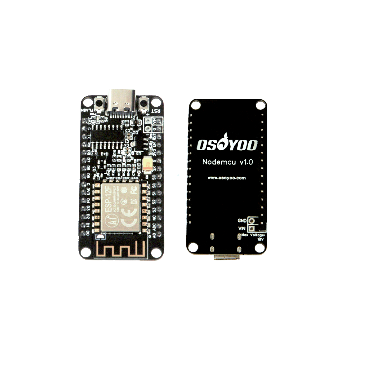
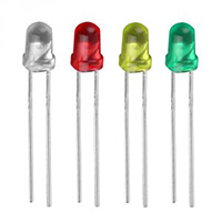
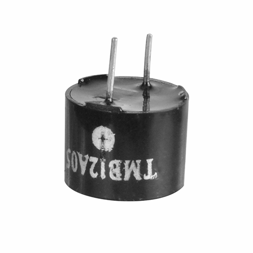
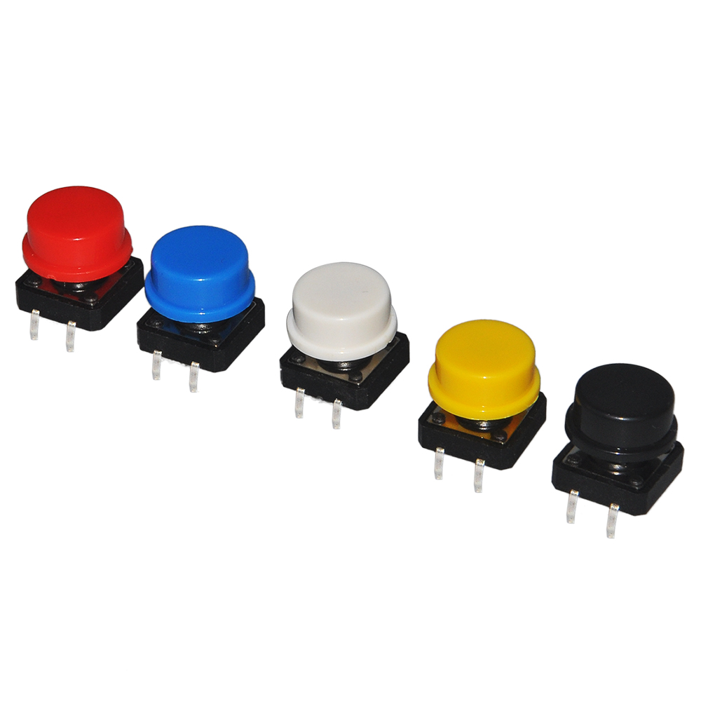
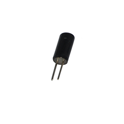
Hardware:
Software:
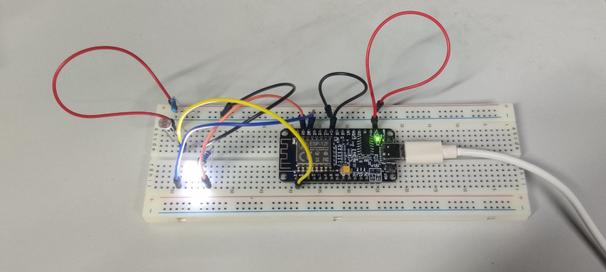
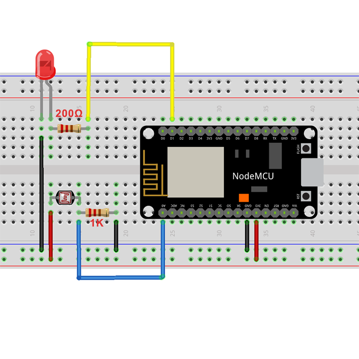
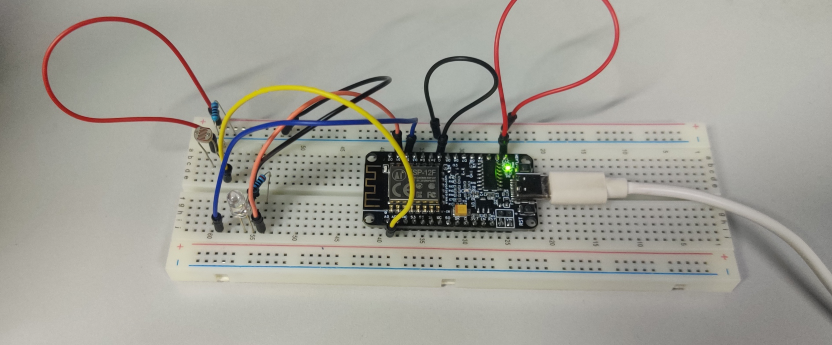
Connection
Upload Sketch
Connect the NodeMCU to computer via USB cable,open this sketch by using Arduino IDE(Version1.6.4+):
Edit the code to fit your own WiFi settings as following operations:
1)Hotspot Configration:
#define STASSID “***” // replace *** with your wifi SSID
#define STAPSK “***” // replace *** with your wifi password
Find above code line,put your own ssid and password on there.
2)UDP local port Settings
// Define the local port to listen on
unsigned int localPort = 8888;
We use the “8888” local port here, you can change it to your own local port.
3)Boad & COM Port Settings
After do that,choose the coresponding board type and port type as below,then upload the sketch to the NodeMCU.
- Board:”NodeMCU 1.0(ESP-12E Module)”
- CPU Frequency:”80MHz”
- Flash Size:”4M (3M SPIFFS)”
- Upload Speed:”115200″
- Port: Choose your own Serial Port for your NodeMCU
Code Introduction:
Here’s a brief overview of its functionality:
- The code establishes a connection to a Wi-Fi network using the provided SSID and password.
- It initializes the UDP server on a specific port to listen for incoming data.
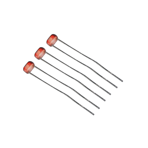
- The light sensor is connected to analog pin A0, and the LED is connected to digital pin D1.
- The code enters the
loop() function, where it continuously reads the light sensor value.
- If the light sensor value exceeds a threshold of 500, the LED is turned on. Otherwise, the LED is turned off.
- The code also listens for incoming UDP packets.
- If a packet is received, it checks the content of the packet.
- If the packet starts with ‘F’, it enables the continuous monitoring of the light sensor and light control.
- If the packet starts with ‘G’, it disables the light sensor monitoring and turns on the LED.
- If the packet starts with ‘H’, it disables the light sensor monitoring and turns off the LED.
The code provides a simple interface to control the light manually through UDP packets while also allowing automatic control based on the light sensor readings.
UDP APP Settings
About how to config the UDP APP,check this link.
Click the setting icon button, you can see the UDP configration page.
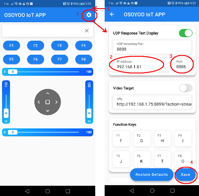
UDP response text display enable button – Enable text play
UDP Incoming Port – Use this port to listen for and accept connections from remote UDP devices, keep the default setting : “8888”
IP address – Change it to your NodeMCU IP address, you can get the IP address from the Arduino IDE Serial Monitor after the code upload down.
Port – Keep the default setting: “8888”.
Keep other settings as default, then click the “Save” button to save your changes.
Running Result
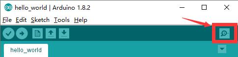
Upload the code to Arduino board, then open Arduino Serial monitor in the upper right corner.
Now please set your Baud Rate to 115200
you will see NodeMCU IP address as following:
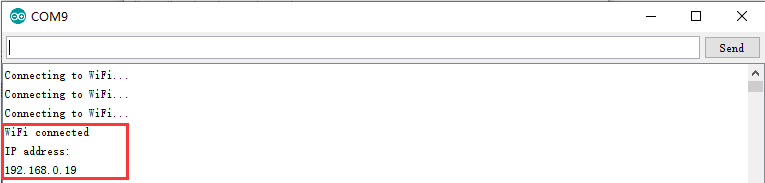
Above result shows your NodeMCU IP address (in my case, 192.168.0.19) , NodeMCU is now waiting for UDP message at port 8888.
Onece the upload done,if wifi hotspot name and password setting is ok and UDP APP is connected.
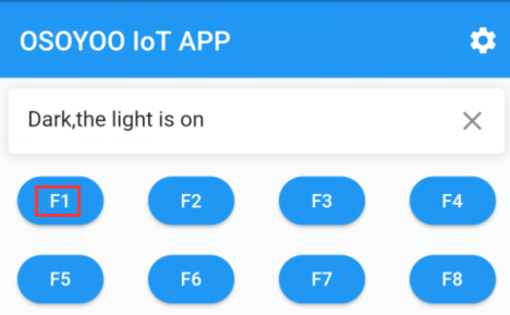
Cover the photosensitive sensor with something and you will see that the LED is lit up.
At the same time,open the UDP APP , you will see the led status as below:
Remove the cover, you will find that the LED is off, but also on the phone to view the LED status.
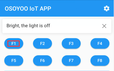
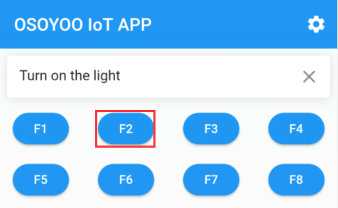
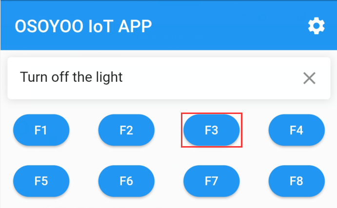
If you want to use the mobile app to control directly, you can press “F2” to turn on the light and “F3” to turn off the light. Of course, when you press “F1” again, the photosensitive sensor will take over the control of the lights again.
If you think you need to adjust the threshold of the photosensitive sensor, you can adjust it yourself in the code. You can also use this kit to create more interesting projects.
FAQ
Question A: Why could OSOYOO IoT APP send message to NodeMCU without even knowing the IP address of the NodeMCU board?
Answer: OSOYOO IoT APP default destination IP is 192.168.1.255 which is a broadcasting IP address. Broadcasting means the APP will send UDP message to all device in the same Wifi Network.
So even we does not set destination IP address to NodeMCU IP, the NodeMCU can still get the message.
Question B: Can I change default sending destination IP address and Port Number of OSOYOO IoT APP?
Yes, you can! Osoyoo IoT APP default IP is 192.168.1.255 and default port is 8888. If you need to change the setting,
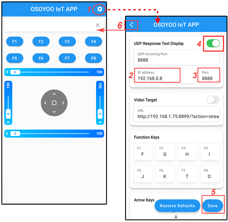
For example, if our NodeMCU IP address is 192.168.0.8, here is the guide to make the change to 192.168.0.8:
1)Open APP, click Setting button in upper right corner
2)Use 192.168.0.8 to replace default IP 192.168.1.255
3)keep default port number 8888 without changing
4)turn on the switch of UDP Response Text Display
5)Click Save button to save the changes you just made
6)Click Back Arrow to go back APP front UI
Question A: I touched my APP F1 key, but no message shows up in my NodeMCU serial monitor, why?
Sometimes, broadcasting IP Address is not necessarily 192.168.1.255, for example, if your NodeMCU IP address is 192.168.0.8, the wifi network broadcasting IP is 192.168.0.255.
So we suggest you replace 192.168.1.255 with 192.168.0.255 to match your network mask of NodeMCU. Of course you can directly set the NodeMCU IP as destination in APP.
If you have any question about OSOYOO NodeMCU products, feel free to contact us or leave comments here.
In next lesson, we will connect a sensor to NodeMCU and send sensor data to another Moquitto client software.
We need to note that ESP8266 is a 2.4G WiFi device, please access to 2.4G network, if you access to a 5G router network, there will be a prompt that the network connection is not successful.
Part details
SKU: DKRK100700