Introduction
In this project, we will go over how to build a smoke sensor circuit with an Arduino board.
The smoke sensor we will use is the MQ-2. This is a sensor that is not only sensitive to smoke, but also to flammable gas.
The MQ-2 smoke sensor reports smoke by the voltage level that it outputs. The more smoke there is, the greater the voltage that it outputs. Conversely, the less smoke that it is exposed to, the less voltage it outputs.
Hardware
- Osoyoo UNO Board (Fully compatible with Arduino UNO rev.3) x 1
- Active Buzzer x 1
- jumpers wires
- USB Cable x 1
- MQ-2 Gas sensor x 1
The MQ-2 smoke sensor is sensitive to smoke and to the following flammable gases:
How does it Work?
The MQ2 has an electrochemical sensor, which changes its resistance for different concentrations of varied gasses. The sensor is connected in series with a variable resistor to form a voltage divider circuit , and the variable resistor is used to change sensitivity. When one of the above gaseous elements comes in contact with the sensor after heating, the sensor’s resistance change. The change in the resistance changes the voltage across the sensor, and this voltage can be read by a microcontroller. The voltage value can be used to find the resistance of the sensor by knowing the reference voltage and the other resistor’s resistance. The sensor has different sensitivity for different types of gasses. The sensitivity characteristic curve is shown below for the different type of gasses.
Example 1: Print Gas status(voltage of sensor) in Serial monitor
| Sensor Pin |
Arduino Pin |
| AO |
A0 |
| Vcc |
5v |
| GND |
GND |

The voltage read from the sensor is displayed in Serial Monitor. This value can be used as a threshold to detect any increase/decrease in gas concentration.
void setup() {
    Serial.begin(9600);
}

void loop() {
    float sensor_volt;
    float sensorValue;

    sensorValue = analogRead(A0);
    sensor_volt = sensorValue/1024*5.0;

    Serial.print("sensor_volt = ");
    Serial.print(sensor_volt);
    Serial.println("V");
    delay(1000);
}
Note: Above line 9 read gas sensor Analog Out(AO) voltage from A0 pin. The value is an integer between 0 to 1024, so we need convert the integer back to a 0 to 5v value in line 10.
After running above code, open the Serial Monitor in your Arduino IDE, you will see Sensor Voltage value .
Example 2: MQ-2 Smoke Alarm
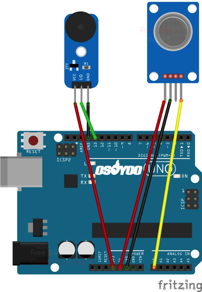
The circuit we will build is shown below.
| Sensor Pin |
Device Pin |
| Buzzer VCC Pin |
5V |
| Buzzer GND Pin |
GND |
| Buzzer AO Pin |
D13 |
| Sensor GND Pin |
GND |
| Sensor VCC Pin |
3.3V |
| Sensor I/O Pin |
A9 |

Download above circuit graph in Fritzing format:
https://osoyoo.com/driver/smarthome/gas-buzzer.fzz
Code for the Arduino MQ-2 Smoke Sensor Circuit
Being that we’ve just gone over the circuit schematic for the smoke sensor circuit, all we need know is the code necessary to upload to the Arduino for this smoke alarm cicrcuit to work.
The code that we need to upload is shown below.
const int sensorPin= 0;
const int buzzerPin= 13;
int smoke_level;

void setup() {
    Serial.begin(9600); //sets the baud rate for data transfer in bits/second
    pinMode(sensorPin, INPUT);//the smoke sensor will be an input to the arduino
    pinMode(buzzerPin, OUTPUT);//the buzzer serves an output in the circuit
}

void loop() {
    smoke_level= analogRead(sensorPin); //arduino reads the value from the smoke sensor
    Serial.println(smoke_level);//prints just for debugging purposes, to see what values the sensor is picking up
    if(smoke_level > 100){ //if smoke level is greater than 100, the buzzer will go off
        digitalWrite(buzzerPin, LOW);//this is LOW-V-trigger buzzer
    }
    else{
        digitalWrite(buzzerPin, HIGH);//Low-V-trigger buzzer will stop alarm in HIGH
    }
}
Download above code:
https://osoyoo.com/driver/smarthome/gas-buzzer.zip
Running above code, then put a gas litter close to the MQ-2 sensor, leak some gas(not necessarily fire the litter), you will see that the buzzer will alarm. If you open Serial monitor, you can see the Gas value . Also you will notice that the buzzer will open alarm when gas value > 100.


