SKU: Model-V-v1.0 | L293DD Dual H-Bridge DC Motor Driver with Servo Ports
The OSOYOO Model V Motor Driver Module is a compact dual H-bridge board built around the L293DD quad half-H bridge IC. It drives two DC motors independently — controlling both speed and direction — making it ideal for wheeled robots and smart vehicle projects.
Electrically it is fully compatible with the popular L298N driver: same ENA / IN1–IN4 / ENB control interface, same H-bridge truth table, and an onboard 5 V regulator. The key improvement is that all motor and power connections use keyed JST-style connectors (K1–K4, CN1–CN2) that physically prevent reverse-polarity wiring errors.
Two dedicated servo signal pins (S, S) on the multipurpose header let you attach a pan-tilt bracket or steering servos without extra hardware. The board is compatible with Arduino Uno / Nano / Mega, ESP32, and Raspberry Pi (via level shifter).
1. Target Application Areas
The Model V is built for robotics, smart vehicle, and automation education projects:
| Application |
Description |
| 2WD / 4WD Robot Car |
Independent left/right motor control for forward, reverse, and tank-style turning. Pair with an ultrasonic sensor for obstacle avoidance. |
| Line-Following Robot |
IR sensors detect the track; PWM adjusts Motor A / Motor B speed in real time to correct heading. |
| Maze-Solving Robot |
Wall-distance sensors combined with differential-drive control allow autonomous maze navigation. |
| Remote-Controlled Car |
Receive commands over Bluetooth (HC-05), Wi-Fi (ESP32), or IR remote and map them to motor speed and direction. |
| Mecanum / Omni Wheel Platform |
Use two Model V boards for four independent wheel motors to achieve holonomic (all-direction) motion. |
| Pan-Tilt Camera / Sensor Arm |
Drive chassis motors while using the on-board servo ports to simultaneously control a camera bracket or ultrasonic sweep arm. |
| DIY Conveyor / Sorting System |
Control two conveyor belts or feeder mechanisms with independent speed and direction. |
| STEM / Classroom Robotics |
L298N-compatible logic, clear silkscreen labels, and keyed connectors reduce student wiring errors — ideal for educational settings. |
2. Features
- Dual H-Bridge Motor Control — Independently drive two DC motors in either direction.
- L293DD Driver IC — Quad half-H bridge with built-in ESD protection; 600 mA continuous / 1.2 A peak per channel.
- L298N-Compatible Control Interface — ENA, IN1, IN2, IN3, IN4, ENB layout; any existing L298N sketch or wiring works without modification.
- PWM Speed Control — Apply
analogWrite() to ENA / ENB for smooth variable-speed control (0–100%).
- Keyed JST Motor Connectors (K1–K4) — Physically prevent reverse-polarity motor connections.
- Keyed JST Power Connectors (CN1, CN2) — Same anti-reverse protection for the main power supply.
- Onboard 5 V Linear Regulator — Converts 7–12 V motor supply to stable 5 V for logic and servo power.
- Motor PWR Jumper — Selects whether the onboard regulator is fed from VIN; remove it to use a separate 5 V logic supply.
- Two Servo Signal Pins — S, S on the multipurpose header for connecting up to two hobby servo motors.
- External Flyback Diodes (D1–D8) — Eight SMD Schottky diodes add extra back-EMF protection beyond the L293DD’s built-in clamps.
- 3.3 V / 5 V Logic Compatible — Works with both 5 V (Arduino Uno/Nano) and 3.3 V (ESP32, Raspberry Pi) controllers.
- Power-On LED Indicator — Instant visual confirmation the board is powered.
- Compact Purple PCB — ~64 × 56 mm with four corner mounting holes for easy chassis integration.
3. Specifications
| Parameter |
Value |
Notes |
| Motor Driver IC |
L293DD |
Quad half-H bridge, SOIC-20 |
| Motor Channels |
2 (Motor A, Motor B) |
Full independent H-bridge per channel |
| Servo Ports |
2 |
Signal pins on multipurpose header |
| Input Voltage (VIN) |
7 V – 12 V DC |
Recommended range for onboard regulator |
| Max Motor Voltage |
36 V (L293DD rated) |
Remove Motor PWR jumper; supply 5 V logic separately if >12 V |
| Logic Supply Voltage |
5 V (onboard) / 3.3 V–5 V (ext.) |
Onboard regulator active when jumper is ON |
| Output Current (continuous) |
600 mA per channel |
Per L293DD datasheet |
| Output Current (peak) |
1.2 A per channel |
Short bursts; ensure adequate ventilation |
| Control Interface |
TTL (3.3 V / 5 V) |
ENA, IN1, IN2, IN3, IN4, ENB |
| Max PWM Frequency |
25 kHz |
L293DD switching limit |
| Onboard Regulator Output |
5 V, ≤ 1 A |
For logic and servo power |
| Motor Connectors |
4 × 2-pin keyed JST (K1–K4) |
Prevents reverse connection |
| Power Input Connectors |
2 × keyed JST (CN1, CN2) |
Polarized VIN & GND |
| Protection |
ESD (L293DD) + flyback diodes D1–D8 |
— |
| Operating Temperature |
0 °C – 70 °C |
— |
| PCB Dimensions |
approx. 64 × 56 mm |
See Mechanical Information |
| Weight |
approx. 20 g |
Without cables |
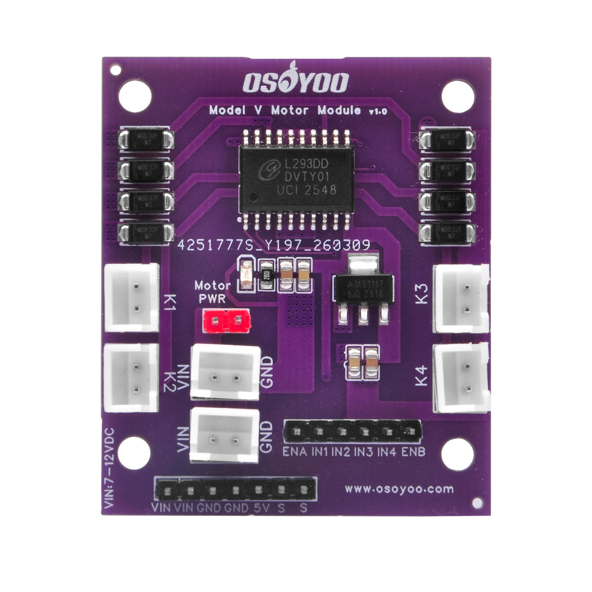
4. Component Overview
The diagram below and the table identify the major components on the Model V board.

Fig. 1 — OSOYOO Model V PCB top view (component reference)
| Label |
Component |
Description |
| U2 |
L293DD Motor Driver IC |
Core driver chip. Quad half-H bridge forming two full H-bridges for Motor A and Motor B. 600 mA continuous / 1.2 A peak per channel; built-in ESD protection. |
| U1 |
5 V Voltage Regulator |
D-PAK linear regulator converting 7–12 V motor supply to stable 5 V for on-board logic, the header 5V pin, and servo power. Active only when the Motor PWR jumper is installed. |
| K1, K2 |
Motor A Output Connectors |
Left side — two keyed JST connectors corresponding to OUT1 and OUT2. Motor A’s two wires connect to K1 and K2. Keyed housing prevents reverse insertion. |
| K3, K4 |
Motor B Output Connectors |
Right side — two keyed JST connectors corresponding to OUT3 and OUT4. Motor B’s two wires connect to K3 and K4. |
| CN1, CN2 |
Power Input Connectors |
Keyed JST connectors for motor power supply (VIN 7–12 V and GND). Two connectors provided for flexible cabling — connect your supply to either one. |
| Motor PWR Jumper |
Regulator Enable Jumper |
Jumper ON (default): onboard regulator powers the 5 V rail from VIN. Jumper OFF: regulator disabled; supply 5 V externally via the header 5V pin. |
| Control Header (6P) |
MCU Control Pins |
Bottom-right through-hole header carrying ENA, IN1, IN2, IN3, IN4, ENB signals from the microcontroller. |
| Multi-purpose Header (7P) |
Power + Servo Header |
Bottom-left through-hole header with VIN pass-through (×2), GND (×2), regulated 5 V output, and two servo signal pins (S, S). |
| D1–D8 |
Flyback Protection Diodes |
Eight SMD Schottky diodes clamping inductive voltage spikes when motor current is switched off — additional protection on top of the L293DD’s internal diodes. |
| LED |
Power Indicator LED |
Illuminates when the board is powered. If the LED is off, check the supply and CN1/CN2 connections. |
5. Pin Description
5.1 Control Header (6-pin) — ENA IN1 IN2 IN3 IN4 ENB
Located on the bottom-right edge. Connect these to digital (and PWM-capable) GPIO pins on your microcontroller.
| Pin |
Direction |
Type |
Description |
| ENA |
Input |
Digital / PWM |
Motor A enable. HIGH = enabled, LOW = coast stop. Use analogWrite(0–255) for speed control. |
| IN1 |
Input |
Digital |
Motor A direction bit 1. HIGH with IN2=LOW → forward. |
| IN2 |
Input |
Digital |
Motor A direction bit 2. HIGH with IN1=LOW → reverse. |
| IN3 |
Input |
Digital |
Motor B direction bit 1. HIGH with IN4=LOW → forward. |
| IN4 |
Input |
Digital |
Motor B direction bit 2. HIGH with IN3=LOW → reverse. |
| ENB |
Input |
Digital / PWM |
Motor B enable. Same behaviour as ENA. |
5.2 Motor Control Truth Table
| ENx |
INx1 |
INx2 |
Motor State |
| HIGH |
HIGH |
LOW |
Forward (clockwise) |
| HIGH |
LOW |
HIGH |
Reverse (counter-clockwise) |
| HIGH |
HIGH |
HIGH |
Brake (fast stop) |
| HIGH |
LOW |
LOW |
Coast (free spin) |
| LOW |
× |
× |
Motor disabled (Hi-Z) |
| PWM |
HIGH |
LOW |
Forward + variable speed |
| PWM |
LOW |
HIGH |
Reverse + variable speed |
ENx = ENA for Motor A (IN1/IN2); ENB for Motor B (IN3/IN4). “×” = don’t care.
5.3 Multi-purpose Header (7-pin) — VIN VIN GND GND 5V S S
| Pin |
Direction |
Description |
| VIN (×2) |
In / Out |
Motor supply voltage (7–12 V) pass-through. Use to power external devices, or as an alternative power input. |
| GND (×2) |
— |
Common ground. Must be connected to microcontroller GND. |
| 5V |
Output |
Regulated 5 V from U1. Powers the microcontroller or sensors. Only available when Motor PWR jumper is ON and VIN is 7–12 V. |
| S (×2) |
Input |
Servo signal pins — connect to PWM-capable GPIO on your microcontroller. Servo power comes from the 5V and GND pins on this same header. |
6. Arduino Getting-Started Tutorial
This tutorial drives a 2-wheel or 4-wheel robot car using the Model V and an Arduino Uno. The same pin assignments and sketch also work with Arduino Nano, Mega, and ESP32.
6.1 Required Hardware
- OSOYOO Model V Motor Driver Module × 1
- Arduino Uno (or Nano / Mega / ESP32) × 1
- DC gear motor, 3–12 V, stall current ≤ 600 mA × 2 (or × 4 for 4WD, same-side motors wired in parallel)
- External DC power supply, 7–12 V, ≥ 1 A (e.g. 4 × AA battery pack, 18650 Li-ion pack, or DC adapter)
- Dupont / jumper wires
- Robot car chassis (optional)
Note: Always connect the Model V GND pin (multipurpose header) to the Arduino GND to create a common ground reference. Without this, control signals have no reference and motor behaviour is unpredictable.
6.2 Wiring
Connect Model V to Arduino Uno as shown below. The Fritzing file (OSOYOO Model V.fzz) included in the product package provides a graphical wiring view.
| Model V Pin / Connector |
Arduino Uno Pin |
Notes |
| ENA (Control Header) |
Pin 5 (PWM ~) |
Motor A speed control |
| IN1 (Control Header) |
Pin 6 |
Motor A direction bit 1 |
| IN2 (Control Header) |
Pin 7 |
Motor A direction bit 2 |
| IN3 (Control Header) |
Pin 8 |
Motor B direction bit 1 |
| IN4 (Control Header) |
Pin 9 |
Motor B direction bit 2 |
| ENB (Control Header) |
Pin 10 (PWM ~) |
Motor B speed control |
| GND (Multi-purpose Header) |
GND |
Essential — common ground |
| 5V (Multi-purpose Header) |
5V (optional) |
Connect only when Motor PWR jumper is ON and you want the board to power the Arduino. Do not connect if Arduino powers itself separately. |
| CN1 or CN2 |
— |
External 7–12 V DC supply (+ to VIN, − to GND) |
| K1 & K2 |
— |
Motor A: left motor wires to K1 and K2 |
| K3 & K4 |
— |
Motor B: right motor wires to K3 and K4 |
4WD Robot Car: Wire the left-side two motors in parallel and connect them to K1 & K2 (Motor A). Wire the right-side two motors in parallel and connect them to K3 & K4 (Motor B). Ensure the combined stall current of the parallel pair does not exceed 1.2 A.
Servo Connection (optional): Servo signal wire → S pin; servo red wire → 5V pin; servo black/brown wire → GND pin. In code, use myServo.attach(pin) with the Arduino pin connected to S.
6.3 Sample Code — Robot Car Demo
The sketch below loops through forward, reverse, left turn, right turn, and stop. Copy it into the Arduino IDE, select your board, and upload.
/*
 *  OSOYOO Model V Motor Driver — Robot Car Demo
 *  Compatible: Arduino Uno / Nano / Mega / ESP32
 *
 *  Wiring (Arduino Uno):
 *    ENA  → Pin 5  (PWM)    ENB  → Pin 10 (PWM)
 *    IN1  → Pin 6           IN3  → Pin 8
 *    IN2  → Pin 7           IN4  → Pin 9
 *    GND  → Arduino GND  (essential!)
 *    VIN  → External 7-12 V DC supply
 *    K1+K2 → Left  motor(s)
 *    K3+K4 → Right motor(s)
 */

// ── Pin definitions ───────────────────────────────────────────────
#define ENA   5    // Motor A enable (PWM speed)
#define IN1   6    // Motor A direction bit 1
#define IN2   7    // Motor A direction bit 2
#define IN3   8    // Motor B direction bit 1
#define IN4   9    // Motor B direction bit 2
#define ENB  10    // Motor B enable (PWM speed)

#define FULL_SPEED  220   // 0-255 drive speed
#define TURN_SPEED  180   // slightly lower for turns

// ── Low-level motor primitives ────────────────────────────────────
void motorA(int spd, bool fwd) {
  analogWrite(ENA, spd);
  digitalWrite(IN1, fwd ? HIGH : LOW);
  digitalWrite(IN2, fwd ? LOW  : HIGH);
}

void motorB(int spd, bool fwd) {
  analogWrite(ENB, spd);
  digitalWrite(IN3, fwd ? HIGH : LOW);
  digitalWrite(IN4, fwd ? LOW  : HIGH);
}

// ── Car movement functions ────────────────────────────────────────
void carForward (int s) { motorA(s,true);  motorB(s,true);  }
void carBackward(int s) { motorA(s,false); motorB(s,false); }
void carLeft    (int s) { motorA(s,false); motorB(s,true);  }
void carRight   (int s) { motorA(s,true);  motorB(s,false); }

void carStop() {
  analogWrite(ENA, 0); analogWrite(ENB, 0);
  digitalWrite(IN1,LOW); digitalWrite(IN2,LOW);
  digitalWrite(IN3,LOW); digitalWrite(IN4,LOW);
}

// ── Setup ─────────────────────────────────────────────────────────
void setup() {
  pinMode(ENA,OUTPUT); pinMode(IN1,OUTPUT); pinMode(IN2,OUTPUT);
  pinMode(ENB,OUTPUT); pinMode(IN3,OUTPUT); pinMode(IN4,OUTPUT);
  carStop();
  Serial.begin(9600);
  Serial.println("OSOYOO Model V — Robot Car Demo");
}

// ── Demo loop ─────────────────────────────────────────────────────
void loop() {
  carForward(FULL_SPEED);  delay(2000);   // forward 2 s
  carStop();               delay(400);
  carBackward(FULL_SPEED); delay(2000);   // backward 2 s
  carStop();               delay(400);
  carLeft(TURN_SPEED);     delay(700);    // spin left ~90°
  carStop();               delay(400);
  carRight(TURN_SPEED);    delay(700);    // spin right ~90°
  carStop();               delay(1500);   // pause, then repeat
}
6.4 Code Notes
- Speed range:
analogWrite() accepts 0–255. Values below ~80 may not provide enough torque to start a loaded motor — increase FULL_SPEED as needed.
- Turn direction: If the car turns opposite to expected, swap the motor wires between K1 and K2 (or K3 and K4) to reverse that motor’s polarity.
- ESP32: The ESP32 Arduino core supports
analogWrite() directly. For finer PWM control use ledcAttach() / ledcWrite() at 1–10 kHz, 8-bit resolution.
- Servo: Add
#include , call myServo.attach(pin) on the pin connected to S, and control it with myServo.write(angle) — fully independent of the motor channels.
7. Mechanical Information
Fig. 2 — PCB 2D layout drawing
| Dimension |
Value |
| PCB Length |
approx. 64 mm |
| PCB Width |
approx. 56 mm |
| PCB Thickness |
1.6 mm (standard FR4) |
| Mounting Holes |
4 × Ø 3.2 mm, one at each corner |
| Mounting Hole Pitch (L) |
approx. 57 mm |
| Mounting Hole Pitch (W) |
approx. 49 mm |
| Tallest Component |
approx. 12 mm (JST connector housing) |
| Weight (bare PCB) |
approx. 20 g |
| PCB Colour |
Purple, ENIG finish |
| Recommended Standoff |
M3 × 8 mm (brass or nylon) |
Mounting tip: Use M3 brass or nylon standoffs through the four corner holes to mount the board on a robot chassis. Keep at least 5 mm clearance below the PCB for component leads.
8. Related Documents
| Document |
File |
Description |
| Circuit Schematic |
SCH_OSOYOO Model V Motor Module v1.0_1-P1_2026-05-14.png |
Full schematic of the Model V board (EasyEDA). |
| PCB 2D Drawing |
PCB-2D_OSOYOO Model V Motor Module v1.0_2026-05-14.png |
Top-view PCB layout with component reference designators. |
| Fritzing Diagram |
OSOYOO Model V.fzz |
Open in Fritzing to view / edit the breadboard wiring diagram. |
| Product Photo |
Motor V实物图.jpg |
High-resolution product photograph. |
| L293DD Datasheet |
— |
Available from Texas Instruments / STMicroelectronics website. |
| OSOYOO Model X (L298N) |
Introduction |
Reference comparison: L298N-based driver with the same control interface. |

Fig. 3 — OSOYOO Model V circuit schematic (EasyEDA)
9. Precautions
⚠ Do not reverse the power supply polarity. Although CN1 and CN2 are keyed, always verify your cable polarity before applying power. Reversed voltage will permanently damage the board.
- Motor current limit: Maximum 600 mA continuous / 1.2 A peak per channel. Check your motor’s stall current before connecting — exceeding this limit will damage the L293DD.
- Supply voltage: Keep VIN between 7 V and 12 V DC. Above 12 V risks the onboard regulator; below 7 V may cause drop-out. For higher motor voltages, remove the Motor PWR jumper and supply 5 V logic externally.
- Motor PWR jumper: Never apply a separate external 5 V to the 5V header pin while the Motor PWR jumper is ON — two voltage sources on the same rail can damage the regulator. Use one or the other, not both.
- Common ground: Always connect Model V GND to Arduino GND. Without a shared ground, control signals have no reference and the motors will behave erratically.
- Heat management: The L293DD and U1 regulator dissipate heat during operation. At near-stall loads or high VIN, ensure adequate ventilation. Reduce load or improve airflow if the chips feel excessively hot.
- PWM frequency: The L293DD is rated to 25 kHz. Arduino’s default
analogWrite() frequency (490–980 Hz) is well within this limit. Do not exceed 25 kHz as it increases switching losses and heat.
- Servo power budget: The onboard regulator can source up to ~1 A. Two loaded servos can draw 400–1000 mA combined. Monitor regulator temperature when running both motors and two servos simultaneously; use an external 5 V supply for the servos if needed.
- Static electricity: Handle the board by its edges. Touch a grounded surface before handling the bare PCB to discharge static.
- Short-circuit protection: The L293DD has no built-in current limiting. A wiring short on the motor outputs can permanently destroy the IC. Double-check all connections before applying power.
OSOYOO Model V DC Motor Driver Module — Product Documentation v1.0 | © OSOYOO |
www.osoyoo.com