- OSOYOO ESP8266 Wifi Module
- OSOYOO W5100 Ethernet IoT learning Kit
- OSOYOO Wifi IoT Learning Kit
- Smart House V2.0 Blynk Control
- Blynk IoT Learning Kit
- LoRa Related
- NodeMCU IoT Kit
- Smart Home Iot Kit
- Smart Home V2.0 UDP APP control
- Project for Raspberry Pi
- FlexiRover Robot Car for Raspberry Pi/Arduino
- IOT kit for raspberry Pi
- Mecanum Wheel Car
- OSOYOO basic kit for Raspberry pi zero
- OSOYOO Robot Car V1 for Raspberry Pi
- OSOYOO Robot Car V2 for Raspberry Pi
- OSOYOO Starter Kit V1 for Raspberry Pi
- OSOYOO Starter Kit V2 for Raspberry Pi
- Screen for Raspberry Pi
- Tank Car for Raspberry Pi
- OSOYOO V4.0 Robot Car for Raspberry Pi
- LilyPad Sewing electronic Kit
- NodeMCU Garden Watering Kit
- OSOYOO 3D Printer Kit
- OSOYOO Advanced Hardware Programming Learning Kit
- OSOYOO Basic Programming Learning Kit
- OSOYOO Cayenne IOT Learning Kit
- OSOYOO Graphical Programming Kit
- Osoyoo Hardware Programming Starter Kit
- OSOYOO IoT Smarthome Kit V0.1
- OSOYOO PNP Programming Learning Kit
- OSOYOO RFID Programming Learning Kit
- Osoyoo Sensor Modules Kit
- OSOYOO Smart Home IoT Kit
- OSOYOO Ultimate Hardware Programming kit
- OSOYOO v3 advanced learning kits
- 16+1 Sensor kit
- Smart Car Kit
- Balance car kit
- Blue Mecanum Wheel Robotic for Arduino Mega2560
- Blue Mecanum Wheel Robotic for Raspberry Pi
- M1.0 Mecanum Wheel Metal Chassis Robotic
- M2.0 Mecanum Wheel Metal Chassis Robotic
- Mars Explorer Mecanum Wheel Robot Kit
- Tank Car Kit V1.0
- Tank Car Kit V2.0
- 2WD Robot Car Starter Kit
- Model-3 V2.0 Robot Car
- OSOYOO Model-3 Robot Learning Kit
- OSOYOO Model-T Robot Car
- OSOYOO Robot Car Starter Kit Tutorial
- OSOYOO Servo Steering Car V3.0 for Arduino MEGA2560
- P3 Servo Steering Robot Car
- SG90 Servo Steering Robot Car
- V2.0 Robot Car kit
- V2.1 Robot car kit
- Sewing eletronic widgets
- Breadboard
- Buzzer
- LED
- Resistor
- Screen
- Sensors
- Temperature sensor
- USB cable
- Wires
- IO-breakout-board-for-ardino-UNO
- IO-breakout-board-for-arduino-nano
- IO-breakout-board-for-arduino-pro-micro
- IO-breakout-board-for-esp32&esp8266
- IO-breakout-board-for-raspberry-pico
- Nano for arduino
- LTG-Nano for Arduino
- Motor driver board
- NodeMCU
- Pro micro for Arduino
- PWM HAT for Rapberry Pi






The command raspi-config on the latest Raspbian Pi does not show I2C or SPI under Advanced Options. I am, however, able to see these options when I use the GUI to get to Raspberry Pi Configuration. However, even enabling I2C and SPI there, I am still not able to get the servo motor to move.
we download the lastest raspbian Lite on the raspberry offical website and we enter sudo raspi-config and find the advance option and enable I2C and SPI.
What’s more, we can config when we enter preference and then in interfaces to enable I2C and SPI.
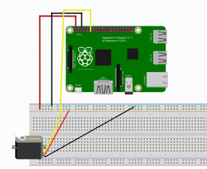
The text on the circuit graph calls for the yellow control wire to be connected to Pin 11 (GPIO 18). But Pin 11 is GPIO 17, and that seems to be what the diagram shows.
We have changed the circuit graph.
After looking at you python code, I need a quick explanation of how duty cycle relates to PWM, since you product spec sheet is uses PWM. I tried a few quick calcs, but I dont seem to be getting the same numbers as those found on your product spec sheet for the servo.
Just trying to learn. Thanks
Awesome article post. Really looking forward to reading more.WWW.batplcbd.com