Introduction
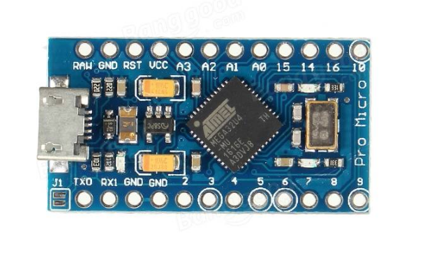
The ProMicro is an Arduino-compatible microcontroller with an ATmega32U4 on board. The USB transceiver inside the 32U4 allows us to add USB connectivity on-board and do away with a bulky external USB interface.
This tiny little board does all of the neat Arduino tricks that you are familiar with: 4 channels of 10-bit ADC, 5 PWM pins, 12 DIOs as well as hardware serial connections Rx and Tx. Running at 16MHz and 5V, this board will remind you a lot of your other favorite Arduino-compatible boards but this little guy can go just about anywhere. There is a voltage regulator on board so it can accept voltage up to 12VDC. If you’re supplying unregulated power to the board, be sure to connect to the ‘RAW’ pin and not VCC.
This latest revision corrects the silk error from the last version of the board so that pin 14 is correctly labeled. We’ve also added a PTC fuse and diode protection to the power circuit and corrected the RX and TX LED circuit.
Note:
The OSOYOO Pro Micro is similar to the Pro Mini except with an ATmega32U4 on board. Like Pro mini,the OSOYOO Pro Micro also comes in two different models i.e, 3.3v and 5v.The OSOYOO Pro Micro 3.3v model has 8MHz crystal oscillator in its board whereas the OSOYOO Pro Micro 5v model has 16MHz oscillator which differentiates them.
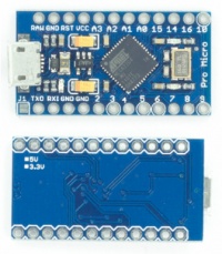
Also notice the backside of board in which the model number is marked either 5v or 3.3v.If both of this signs are failed,check the jumper(J1) at the top left corner of the board which is closed for 5V and open for 3.3V.
Features:
- ATmega32U4 running at 5V/16MHz.
- Supported under Arduino IDE v1.0.1.
- On-Board micro-USB connector for programming.
- 4 x 10-bit ADC pins.
- 12 x Digital I/Os (5 are PWM capable).
- Rx and Tx Hardware Serial Connections.
Suggested Reading
Before delving into this tutorial, here are some concepts you should be familiar with. If you’re not, consider checking out the related tutorial first.
Pinouts
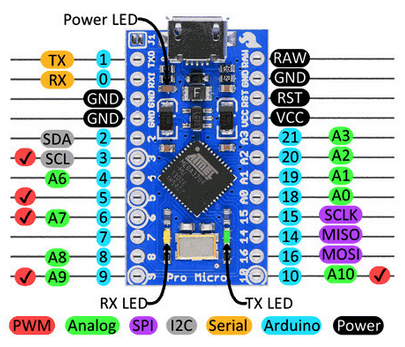
Power Pins
There are a variety of power and power-related nets broken out:
- RAW is the unregulated voltage input for the OSOYOO Pro Micro. If the board is powered via USB, the voltage at this pin will be about 4.8V (USB’s 5V minus a Schottkey diode drop). On the other hand, if the board is powered externally, through this pin, the applied voltage can be up to 12V.
- VCC is the voltage supplied to the on-board ATmega32U4. This voltage will depend on whether you’re using a 3.3V/8MHz OSOYOO Pro Micro or a 5V/16MHz version, it’ll be either 3.3V or 5V respectively. This voltage is regulated by the voltage applied to the RAW pin. If the board is powered through the ‘RAW’ pin (or USB), this pin can be used as an output to supply other devices.
- RST can be used to restart the OSOYOO Pro Micro. This pin is pulled high by a 10k&Ohm; resistor on the board, and is active-low, so it must be connected to the ground to initiate a reset. The OSOYOO Pro Micro will remain “off” until the reset line is pulled back to high.
- GND, of course, is the common, ground voltage (0V reference) for the system.
I/O Pins
The OSOYOO Pro Micro’s I/O pins – 18 in all – are multi-talented. Every pin can be used as a digital input or output, for blinking LEDs or reading button presses. These pins are referenced in the Arduino IDE via an integer value between 0 and 21. (The A0-A3 pins can be referenced digitally using either their analog or digital pin number).
Nine pins feature analog to digital converters (ADCs) and can be used as analog inputs. These are useful for reading potentiometers or other analog devices using the analogRead([pin]) function.
There are five pins with pulse width modulation (PWM) functionality, which allows for a form of analog output using the analogWrite([pin], [value]) function. These pins are indicated on-board with a faint, white circle around them.
There are hardware UART (serial), I2C, and SPI pins available as well. These can be used to interface with digital devices like serial LCDs, XBees, IMUs, and other serial sensors.
The OSOYOO Pro Micro has five external interrupts, which allow you to instantly trigger a function when a pin goes either high or low (or both). If you attach an interrupt to an interrupt-enabled pin, you’ll need to know the specific interrupt that pin triggers: pin 3 maps to interrupt 0, pin 2 is interrupt 1, pin 0 is interrupt 2, pin 1 is interrupt 3, and pin 7 is interrupt 4.
On-Board LEDs
There are three LEDs on the OSOYOO Pro Micro. One green LED indicates whether power is present.
The other two LEDs help indicate when data is transferring over USB. One LED represents USB data coming into (RX) the the OSOYOO Pro Micro, and the other LED indicates USB data going out (TX).
How to Power the OSOYOO Pro Micro
As the OSOYOO Pro Micro’s main feature is its innate USB functionality, the most common way to power it is via USB. In this setup, a 5V OSOYOO Pro Micro will be powered directly from the USB bus. The other end of the USB cable can be connected to either a computer, USB hub, or a USB wall adapter, which can (in most cases) provide more power.
Alternatively, if your OSOYOO Pro Micro is living out in the wild, out of reach of USB cables, it can be powered through either the ‘RAW’ or ‘VCC’ pins. A supply going into the ‘RAW’ pin will be regulated down to the correct operating voltage . To be safe, it shouldn’t be any higher than 12V, and it should be at least 1V more than the OSOYOO Pro Micro’s operating voltage (e.g. >6V for a 5V OSOYOO Pro Micro).
If you power the OSOYOO Pro Micro through the ‘VCC’ pin, keep in mind that this signal is unregulated. Only use this if you have a clean, regulated 5V supply to connect to it.
Resources:
Getting Started with the OSOYOO Pro Micro
The OSOYOO Pro Micro boards use an ATmega32U4 to offer you more functionalities compared to Uno.
The OSOYOO Pro Micro are programmed using the Arduino Software (IDE), our Integrated Development Environment common to all our boards and running both online and offline. For more information on how to get started with the Arduino Software visit the Getting Started page.
Use your OSOYOO Pro Micro on the Arduino Web IDE
All Arduino and Arduino compatible boards, including this one, work out-of-the-box on the Arduino Web Editor, no need to install anything.
The Arduino Web Editor is hosted online, therefore it will always be up-to-date with the latest features and support for all boards. Follow this simple guide to start coding on the browser and upload your sketches onto your board.
Use your OSOYOO Pro Micro on the Arduino Desktop IDE
If you want to program your Leonardo, Leonardo ETH and Micro while offline you need to install the Arduino Desktop IDE.
Installing drivers for OSOYOO Pro Micro
Drivers should be automatically installed plugging with an USB cable the board to your PC, but with some version of the Windows operative system (like Windows 7, Vista and 10) it can happen that your board won’t be recognized and you will get the message Unknown USB device. It is so necessary to manually install them following the guide Manually install Drivers on Windows.
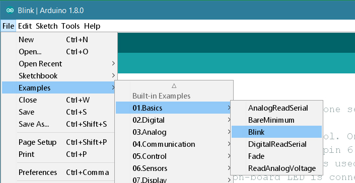
Open the Blink example
Now that you’ve set up your online IDE let’s make sure your computer can talk to the board, it’s time to make sure you can upload a program. To do that let’s open the LED blink example sketch: File > Examples > 1.Basics > Blink.
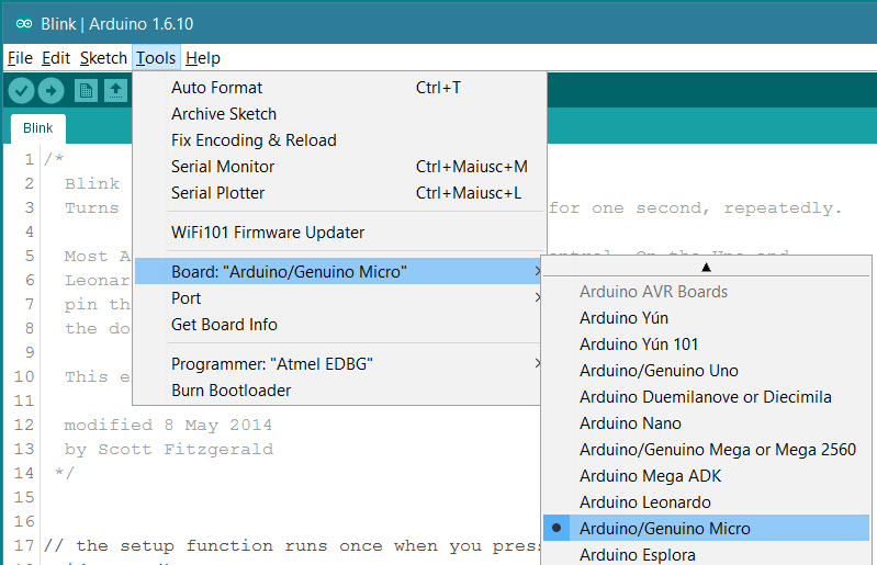
Select your board
You’ll need to select your board in the Tools > Board menu:
osoyoo-datasheet/master/Osoyoo_Pro_Micro
- Arduino/Genuino Micro
according to the board you have.
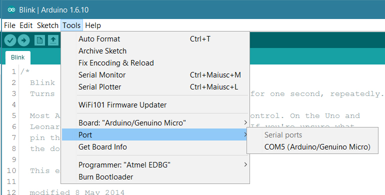
Select your serial port
Select the serial device of the board from the Tools > Serial Port menu.
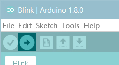
Upload and Run your first Sketch
Click the Upload button in the upper left to load and run the sketch on your board:
After the compilation and upload process, you should see the message Done Uploading and the built-in LED of the board should start blinking.
Tutorials
Now that you have set up and programmed your OSOYOO Pro Micro board, you may find inspiration in our official example website or Arduino Project Hub tutorial platform.