概要
OSOYOO UART LoRaワイヤレスモジュールは、Arduinoモジュールのフォームファクタに搭載された長距離トランシーバーで、オープンソースライブラリをベースにしています。OSOYOO UART LoRaワイヤレスモジュールは、ユーザーがデータを送信し、低データレートで非常に長距離に到達することができます。
OSOYOO UART LoRaワイヤレスモジュールは、灌漑システム、スマートメーター、スマートシティ、スマートフォン検出、ビルディングオートメーションなどのプロフェッショナルなワイヤレスセンサーネットワークアプリケーションをターゲットとしています。
このチュートリアルでは、UART LoRaモジュールをArduinoボードで使用する方法を紹介します。これらの簡単なポイント・ツー・ポイントの例を通して、LoRaワイヤレスについてより深く知ることができるでしょう。
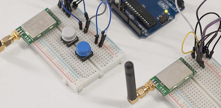
このLoRaモジュールは、TXピンとRxピンを持つシリアルインターフェースで動作します。そのため、Arduinoに簡単に組み込むことができ、Arduino開発者がすでに知っているシリアルの機能を使うことができる。
通信距離は、使用するアンテナ、環境条件、無線周波数と磁気の干渉に応じて、最大3キロに達することができます。
電源は3,3Vまたは5Vで、シリアル通信はTTLで5Vです。これは、Arduinoボードやesp8266のような他の3,3Vと安全な接続で行うことができることを意味します。
このモジュールには4つの動作モードがある。最も基本的なモードは、単純な通信のためのノーマルモードです。この場合、M0ピンとM1ピンをGND(レベル0)にする必要があります。
準備
ハードウエア
工作に必要なものは以下の通り:
- Arduino UNO (ここではOSOYOO UNOボードを使用) x 2
- OSOYOO UART LoRaワイヤレス・モジュール(433MHZ) x 2
- OSOYOO 433MHZ LoRa SMAアンテナ x 2
- スイッチボタン×2
- LED×1個
- 200Ω抵抗
- ブレッドボード
- ジャンパー
ソフトウェア
Arduino IDE
Arduinoライブラリ SoftwareSerial.h
使用上の注意
無線リンクの品質と性能は、環境に大きく依存することに注意する必要があります。プロジェクトに適した周波数のLoRaモジュールを選択したことを確認してください。LoRaモジュールに対応する周波数のアンテナがあることを確認してください。
より良いパフォーマンスを得るには
- 屋外環境。
- 障害物がないこと。
- ISM 868(/868/915)MHz帯で高レベルの電波干渉がないこと。
- 地上から1メートル以上離れていること。
無線性能は以下の場合に低下します:
- 障害物:建物、木…
- 建物内の環境。
- ISM 433(/868/915)MHz帯が他の技術で使用されている場合。
無線通信は通常、地形条件が悪いと途絶える。非常に小さな丘であっても、丘越しの通信は通常不可能である。
例
ARDUINOによる基本UART LORAモジュール通信
この例では、2つのOSOYOO UART LoRaワイヤレスモジュールを使って信号を送受信します:
接続
2つのOSOYOO UART LoRaワイヤレスモジュールをArduinoボードに接続し、USBケーブルでコンピュータに接続します。
| Arduino UNO |
OSOYOO UART LoRa無線モジュール |
| GND |
M0 |
| GND |
M1 |
| D3 |
RXD |
| D2 |
TXD |
| NC |
AUX |
| 5V |
VCC |
| GND |
GND |
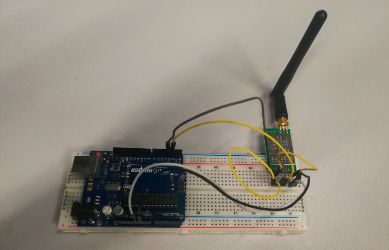
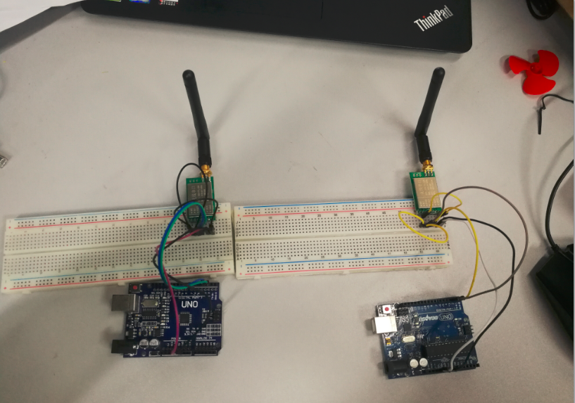
下図のように、左側のOSOYOO UART LoRaワイヤレスモジュール+OSOYOO UNOをサーバ(デバイスA)として信号を送信し、右側のOSOYOO UART LoRaワイヤレスモジュール+OSOYOO UNOをクライアント(デバイスB)として信号を受信します。
コードプログラム
送信と受信を同時に行うには、2つのArduino IDEが必要です。そこで、Arduino IDEのアイコンを2回クリックします。両方のArduino IDEを同時に実行し、両方のArduino IDEにコードをコピーします。
#include <SoftwareSerial.h>

SoftwareSerial mySerial(2, 3); //TX, RX
// (Send and Receive)

void setup() {
  Serial.begin(9600);
  mySerial.begin(9600);
}

void loop() {


  if(Serial.available() > 0){//Read from serial monitor and send over  OSOYOO UART LoRa wireless module
    String input = Serial.readString();
    mySerial.println(input);
  }

  if(mySerial.available() > 1){//Read from  OSOYOO UART LoRa wireless module and send to serial monitor
    String input = mySerial.readString();
    Serial.println(input);
  }
  delay(20);
}
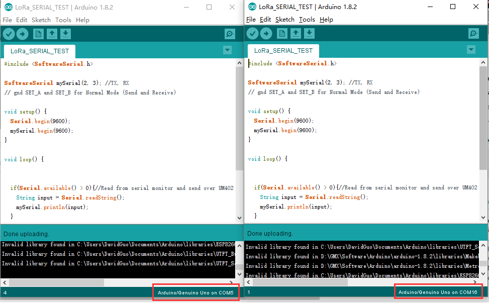
- コードはGithubからコピーまたはダウンロードしてください。
- ボードの種類 “Arduino UNO/ Genuino UNO”
- ポート:2つのOSOYOO UNOボードに対応するCOMポートを選択してください。
以上の操作が完了したら、アップロードボタンをクリックします。
アップロードが完了したら、それぞれのシリアルモニタを開いてください。ここで、シリアルモニターに何か文字を入力してみて、それが別の側に表示されるのを待ちます。例えばこの写真では、シリアルモニターCOM16に “123 “と入力すると、それがシリアルモニターCOM5に送られて表示されます。

OSOYOO UART LORAワイヤレスモジュールを使ってLEDを遠隔操作する
これは、LoRa経由でリモートのArduinoからデータを取得する方法を示す例です。この場合、2つの回路があります。1つはデータの送信用、もう1つは受信用です。
送信回路
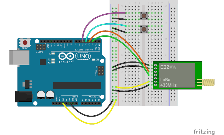
送信回路は、Arduino、2つの押しボタン、OSOYOO UART LoRaモジュールで構成されています。
受信回路
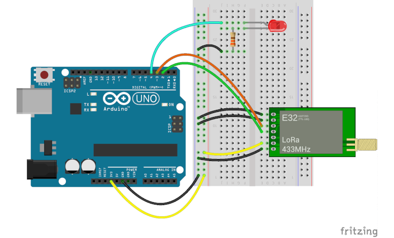
受信回路は、Arduino、LEDモジュール、抵抗、OSOYOO UART LoRaモジュールで構成されます。
注意:プロジェクトに適した周波数のLoRaモジュールを選択したことを確認してください。LoRaモジュールに対応する周波数のアンテナがあることを確認してください。
コードプログラム
トランスミッターのコード
送信機のプログラミングは、それぞれのボタンが押されたことに応じて、2つの文字列 “on “と “off “をプロトコル・シリアルで送信することを目的としています。以下のコードを参照してください(またはGithubからダウンロードしてくださいb):
#include <SoftwareSerial.h>

#define BTN1  4
#define BTN2  5

SoftwareSerial loraSerial(2, 3); // TX, RX

String turnOn = "on";
String turnOff = "off";


void setup() {
  pinMode(BTN1, INPUT_PULLUP);
  pinMode(BTN2, INPUT_PULLUP);
  Serial.begin(9600);
  loraSerial.begin(9600);

}

void loop() {

  if(digitalRead(BTN1) == 0) {
    loraSerial.print(turnOn);
    while(digitalRead(BTN1) == 0);
    delay(50);
  }

  if(digitalRead(BTN2) == 0) {
    loraSerial.print(turnOff);
    while(digitalRead(BTN2) == 0);
    delay(50);
  }
}
受信機のコード
受信機のプログラミングの目的は、送信機から送られてくる文字列を待つことである。文字列を “on “で受信すると、LEDを点灯させる。文字列 “off “を受信したらLEDを消す。以下のコードを参照(またはGithubからダウンロード):
#include <SoftwareSerial.h>

#define LED1  4

SoftwareSerial loraSerial(2, 3); // TX, RX

void setup() {
  pinMode(LED1, OUTPUT);
  Serial.begin(9600);
  loraSerial.begin(9600);
}

void loop() {
  if(loraSerial.available() > 1){
    String input = loraSerial.readString();
    Serial.println(input);
    if(input == "on") {
      digitalWrite(LED1, HIGH);
    }
    if(input == "off") {
      digitalWrite(LED1, LOW);
    }
  }
  delay(20);
}
実行結果

上記の動作が完了したら、D4に接続されているボタンを押すと受信側のLEDが点灯し、D5に接続されているボタンを押すと受信側のLEDが消灯します。
参考
Osoyoo 長距離無線トランシーバー Uart LoRaモジュール
LoRa無線ネットワークとは?
LoRaアーキテクチャ
LoRaセキュリティ
LoRaWAN周波数バンド


merhaba bu çalışmanın arduino mega 2560 megaya göre kodları varmı ?
This test is based on the UNO, you can also use mega2560,Be careful when using arduino other than uno since not all pins can support SoftwareSerial!
The Module data sheet says that the “Communication level (V)” (I assume that means voltage on the TX RX pins) is maximum 3.3v otherwise you risk burning out the module yet here your example shows them connected to 5V lines without any level converters. So are the pins 5V safe despite what the data sheet says?
When using our LoRa module, we need to follow the product tutorial to connect the rx pin of the module to the tx pin of mcu, and the tx pin of the module to the rx pin of mcu
As you can see from the product datasheet, the power supply over 5v can guarantee the best performance, voltage over 5.2v may cause damage to the module, so, The power supply range is 2.3v-5.2v
The communication voltage level over 5v may at risk of burning down, the communication voltage range is 2.3-3.6v, 3.3v is the best
There, Use 5v power supply to supply power to the module, and use mcu with 3.3v level will be the best choice.
That doesn’t clarify why your example shows the module connected to 5V data lines are you saying your example is incorrect?
thanks for the article
I followed the steps, but communication takes place when the sending module is de-energized. It is really interesting as if it sends and collects packets, then when the sender closes, it prints all the packets it receives.
Can you help?
Uhm… I haven’t encountered such a situation yet. Can you describe it in more detail?
Thanks for the article. Do you have an exanple of sensor data transmission with these modules, i.e: DHT 11, GY-91?
We provide basic module usage methods and sensor usage tutorials. Wouldn’t it be more fun to make them work together?
Yes, it is exactly what I was looking for. . .A code program for trasmitting sensor data between arduinos using UART LoRa wireless module(433MHZ)…
Hi. Thanks for this afticle.
And My LoRa is LSD4WN-2L217M90 that using same chip XS1278.
The difference is that I used esp32 and version 2.3 of the arduino IDE to use SoftwareSerial.
I would appreciate it if you could let me know what else I should check.