Introduction
During the building of your projects for Arduino, you’ll often need to read the output data directly from a LCD display. In this lesson we will show how to mount a LCD display on your Arduino using the I2C communication. Finally you will see how to program it with a simple example showing how to display text on the display.
Preparations
HARDWARE
- Osoyoo UNO Board (Fully compatible with Arduino UNO rev.3) x 1
- I2C LCD 1602 Display x 1
- F/M jumpers
- USB Cable x 1
- PC x 1
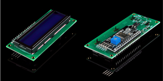
About I2C LCD 1602 Display
The integration of an LCD display greatly facilitates the interactivity of the project you are developing, allowing the user to directly read some output parameters. These values can be either a simple text or numerical values read by the sensors, such as temperature or pressure, or even the number of cycles that the Arduino is performing.
However, these displays have a small problem. When they are connected to a microcontroller (such as Arduino for example), these displays require virtually many connection PINs occupying practically almost all available IO and leaving the multiprocessor few outputs for any other devices and sensors. This problem has been solved thanks to the communication on the I2C bus.
The LCD1602 display has an integrated microchip that manages this type of communication, and then all of the input and output information are limited to only two PINs (excluding power supply). I2C is a type of serial bus developed by Philips, which uses two bidirectional lines, called SDA (Serial Data Line) and SCL (Serial Clock Line). Both must be connected via pulled-up resistors. The usage voltages are standard as 5V and 3.3V.
The blue potentiometer on the I2C LCD1602 (see the figure below) is used to adjust the backlight for better display.And there is a jumper on the board, if you take away this jumper , the backlight will aways be off.
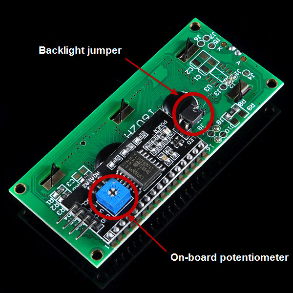
For the usagage of other functions, pleae refer to the “LiquidCrystal_I2C.h” in the sourcecode of I2C LCD library.
Connection
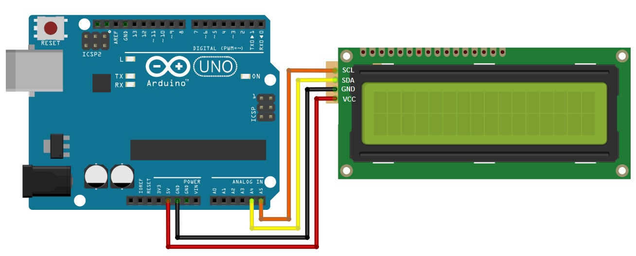
Before you write the code you have to build the circuit. To do this, connect the pins as follows:
| Osoyoo UNO |
LCD1602 |
| GND |
GND |
| 5V |
VCC |
| A4 |
SDA |
| A5 |
SCL |
Note:
- For Mega2560: the I2C connections are on SDA=20 and SCL=21. So go ahead and wire these up, along with the two power leads to the 5V and GND terminals.
- For Arduino Leonardo: connect SDA to digital pin 2 and SCL to digital pin 3 on your Arduino.
From sketches of Fritzing, you can look at the connections to be done in a simpler way:
CODE PROGRAM
After above operations are completed, connect the Arduino board to your computer using the USB cable. The green power LED (labelled PWR) should go on.Open the Graphical Programming software Mixly and follow the next operations:
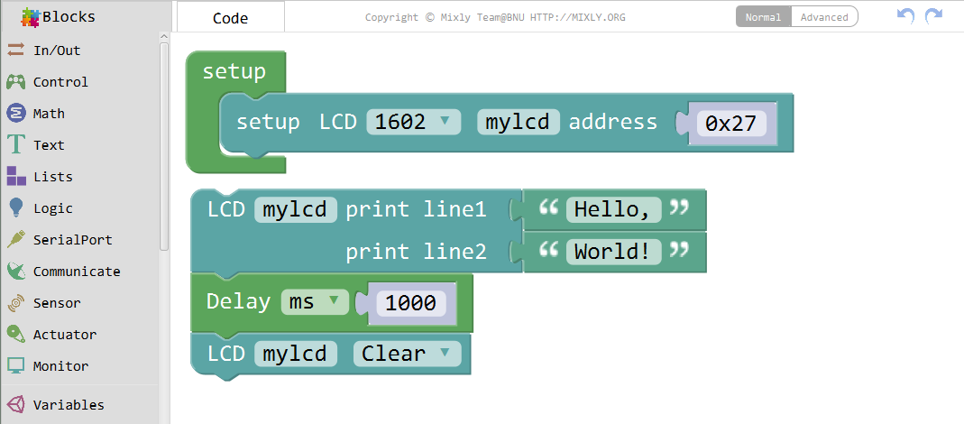
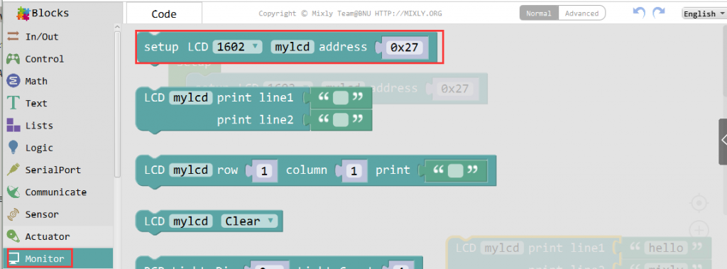
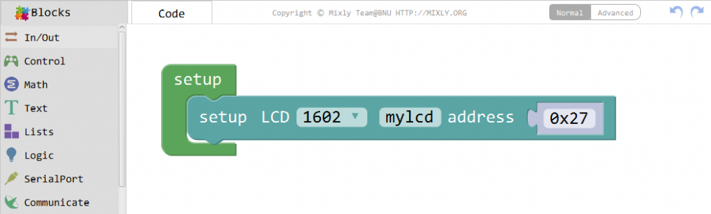
Click the Monitor block and drag the following code to blank area, choose the 1602 LCD and set the address as 0x27.
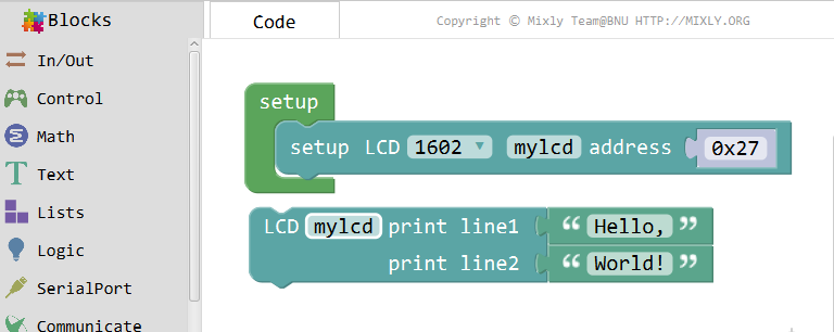
Add LCD print for this experiment, line 1 print”Hello,”, line 2 print “World!”.
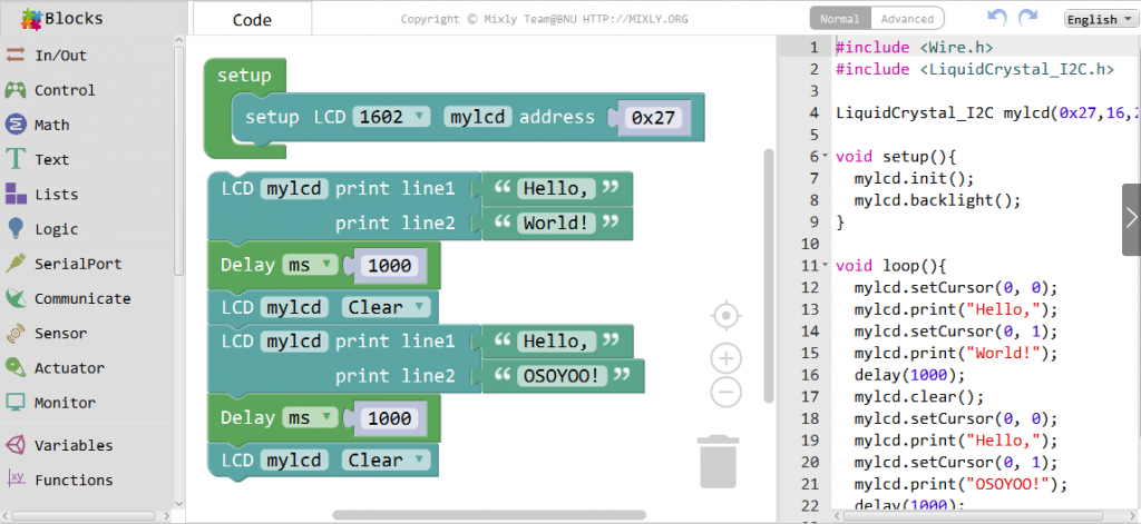
Now, add Delay function and LCD Clear,

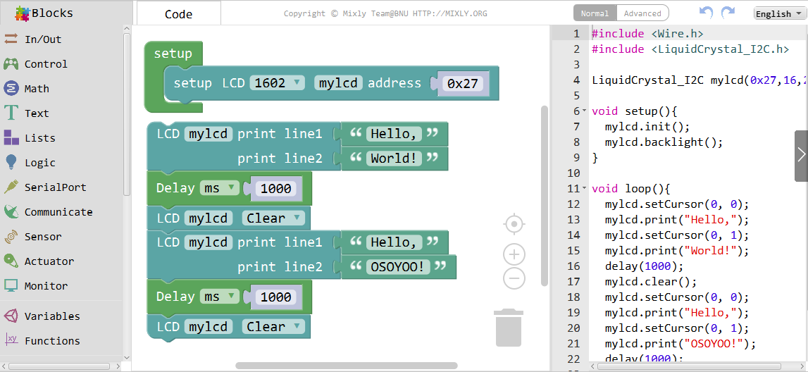
Then, you can print other letters as below:
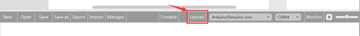
Click Save aftogramming is done. Select the board type and serial port before uploading. For instause a Uno board, just select Arduino/Genuino Uno: if you use a Mega2560, select Arduino/Genuino Mega or Mega2560. 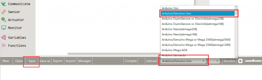
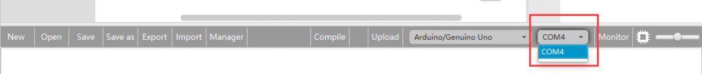
Select the serial device of the Arduino board from the COM menu. This is likely to be COM3 or higher (COM1 and COM2 are usually reserved for hardware serial ports). To find out, you can disconnect your Arduino board and re-open the menu; the entry that disappears should be the Arduino board. Reconnect the board and select that serial port.
Next,upload the code. If the uploading fails, check and correct the code according to the prompts.

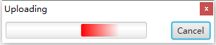
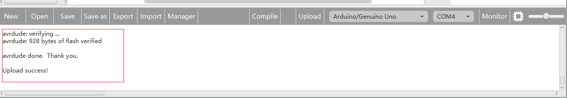
Finally, the staus will change to ‘Upload success!’.

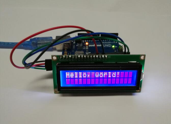
Running Result
A few seconds after the upload finishes, you should now see your I2C LCD1602 display the static characters: “Hello, World!”,next, the LCD will be cleared, and then the “Hello, OSOYOO!” will be displayed.