Introduction
A passive infrared sensor (PIR Motion sensor) is an electronic sensor that measures infrared (IR) light radiating from objects in its field of view. They are most often used in PIR-based motion detectors. So, it can detect motion based on changes in infrared light in the environment. It is ideal to detect if a human has moved in or out of the sensor range. In this lesson we will learn how a PIR Sensor works and how to use it with the Arduino Board for detecting motion.
Preparations
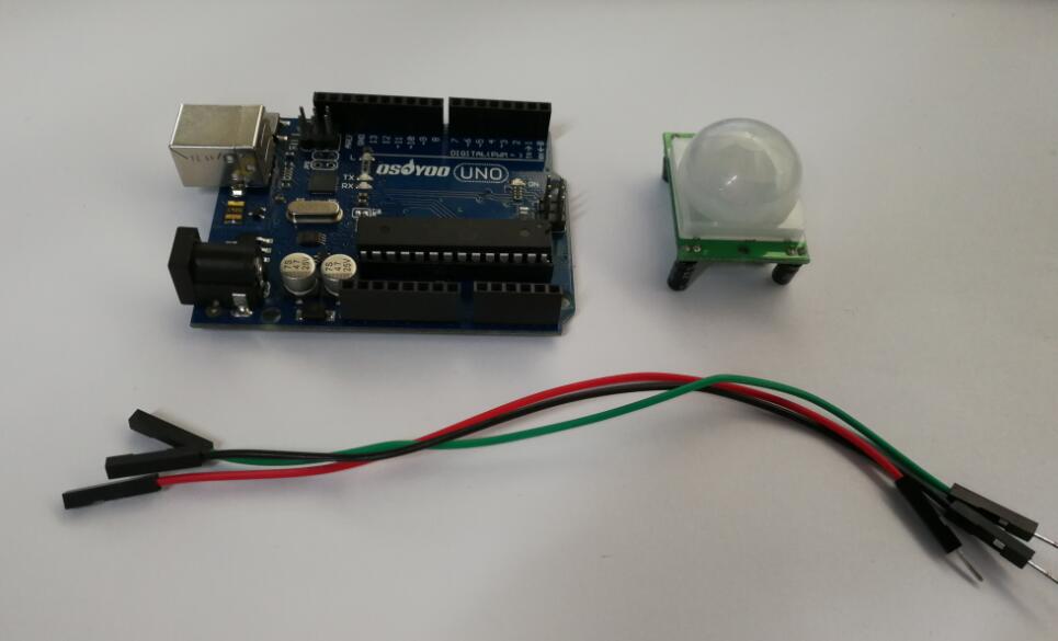
HARDWARE
- Osoyoo UNO Board (Fully compatible with Arduino UNO rev.3) x 1
- PIR Motion sensor x 1
- Relay x 1
- Breadboard x 1
- Jumpers
- USB Cable x 1
- PC x 1
About PIR Motion sensor
OVERVIEW
PIR Motion Sensors allow you to sense motion, almost always used to detect whether a human has moved in or out of the sensors range. They are small, inexpensive, low-power, easy to use and don’t wear out. For that reason they are commonly found in appliances and gadgets used in homes or businesses. They are often referred to as PIR, “Passive Infrared”, “Pyroelectric”, or “IR motion” sensors.
Use this Arduino motion sensor to build burglar alarm systems, home automation systems, or any simple gadget that prevents people from getting into your room!
SPECIFICATIONS
- Working voltage: 4.5V to 20V
- Output: High: 3.3V, Low: 0V
- Detection angle: Approximately 120 degrees
- Range: Adjustable, up to 7m
- Trigger modes: L unrepeatable trigger / H repeatable trigger (default)
- Dwell time: (Stay-ON time) adjustable between 5-300 Seconds. –– it can be further increased by increasing the value of the CY1-Timing capacitor on pin 4 of the IC
- Operating Temperature: -20 – +80 Degrees C.
- PCB Dimensions: 33x25mm, 14mm High not including the Lens; Lens: 11mm high, 23mmDiameter.
- Weight: 6g
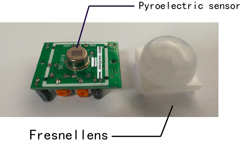
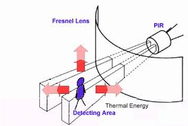
PIRs are basically made of a pyroelectric sensor (which you can see above as the round metal can with a rectangular crystal in the center), which can detect levels of infrared radiation. Everything emits some low level radiation, and the hotter something is, the more radiation is emitted. The sensor in a motion detector is actually split in two halves. The reason for that is that we are looking to detect motion (change) not average IR levels. The two halves are wired up so that they cancel each other out. If one half sees more or less IR radiation than the other, the output will swing high or low.
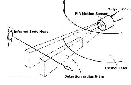
This sensor is then placed behind a multifaceted lens (a Fresnel lens) that “chops up” the view of the world into smaller cones of heightened visibility and intervening areas of lessened visibility thus widening the useful viewing /detection angle dramatically.
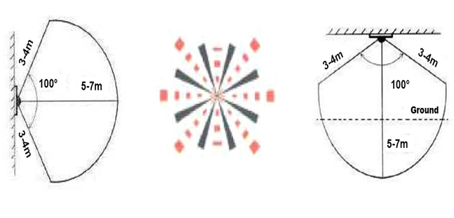
PIR SENSING ANGLE DIAGRAM:
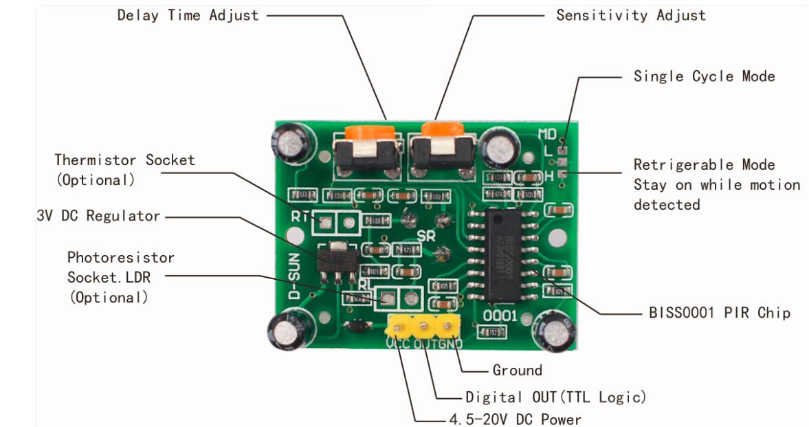
Along with the pyroelectic sensor is a bunch of supporting circuitry, resistors and capacitors. It seems that most small hobbyist sensors use the BISS0001 (“Micro Power PIR Motion Detector IC”), undoubtedly a very inexpensive chip. This chip takes the output of the sensor and does some minor processing on it to emit a digital output pulse from the analog sensor.
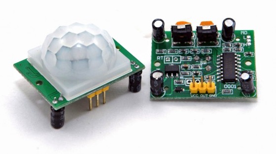
Our PIR Motion Sensors looked like this:
| Pin or Control |
Function |
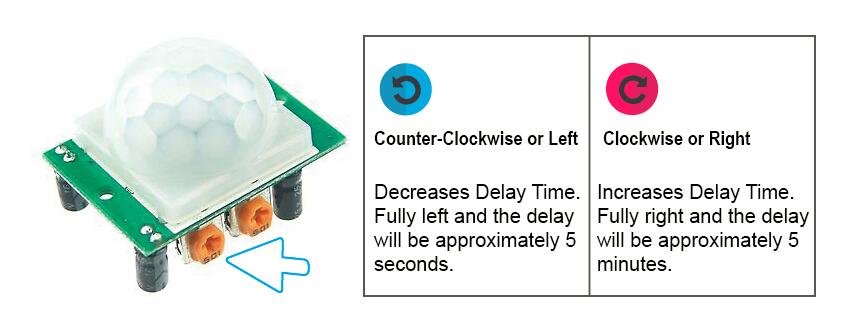
| Delay Time Adjust |
Sets how long the output remains high after detecting motion…. Anywhere from 5 seconds to 5 minutes. |
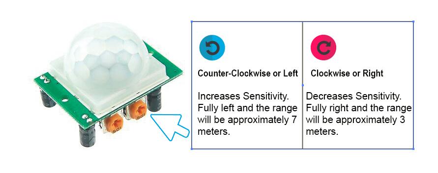
| Sensitivity Adjust |
Sets the detection range…. from 3 meters to 7 meters |
| Ground pin |
Ground input |
| Digital Output Pin |
Low when no motion is detected.. High when motion is detected. High is 3.3V |
| Power Pin |
4.5 to 20 VDC Supply input |
HOW DOES IT WORK?
Here, we are using a PIR motion sensor. PIR stands for Passive InfraRed. This motion sensor consists of a fresnel lens, an infrared detector, and supporting detection circuitry. The lens on the sensor focuses any infrared radiation present around it towards the infrared detector. Our bodies generate infrared heat and as a result, this gets picked up by the motion sensor. The sensor outputs a 5V signal for a period of one minute as soon as it detects the presence of a person. It offers a tentative range of detection of about 6-7 m and is highly sensitive.
When the PIR motion sensor detects a person, it outputs a 5V signal to the Arduino. Thus, an interrupt on Arduino is triggered. We define what the Arduino should do as it detects an intruder.
SENSITIVITY ADJUSTMENT
As mentioned, the adjustable range is from approximately 3 to 7 meters. The illustration below shows this adjustment. You may click to enlarge the illustration.
DELAY TIME ADJUSTMENT
The time delay adjustment determines how long the output of the PIR sensor module will remain high after detection motion. The range is from about 5 seconds to five minutes. The illustration below shows this adjustment.
TRIGGER MODE SELECTION PART
The trigger mode selection jumper allows you to select between single and repeatable triggers. The affect of this jumper setting is to determine when the time delay begins.
- SINGLE TRIGGER – The time delay begins immediately when motion is first detected.
- REPEATABLE TRIGGER – Each detected motion resets the time delay. Thus the time delay begins with the last motion detected.
5 SECONDS OFF AFTER TIME DELAY COMPLETES – IMPORTANT
The output of this device will go LOW (or Off) for approximately 5 seconds after the time delay completes. In other words, all motion detection is blocked during this three second period.
For Example:
- Imagine you’re in the single trigger mode (see below) and your time delay is set 5 seconds.
- The PIR will detect motion and set it high for 5 seconds.
- After five seconds, the PIR will sets its output low for about 3 seconds.
- During the three seconds, the PIR will not detect motion.
- After three seconds, the PIR will detect motion again and detected motion will once again set the output high and the output will remain on as dictated by the Delay Time adjustment and trigger mode selection.
Examples
PIR MOTION SENSOR CONTROL LED
In this project you’re going to create a simple circuit with an Arduino and PIR motion sensor that can detect movement. An LED will light up when movement is detected.
Connection
Build the circuit as below:
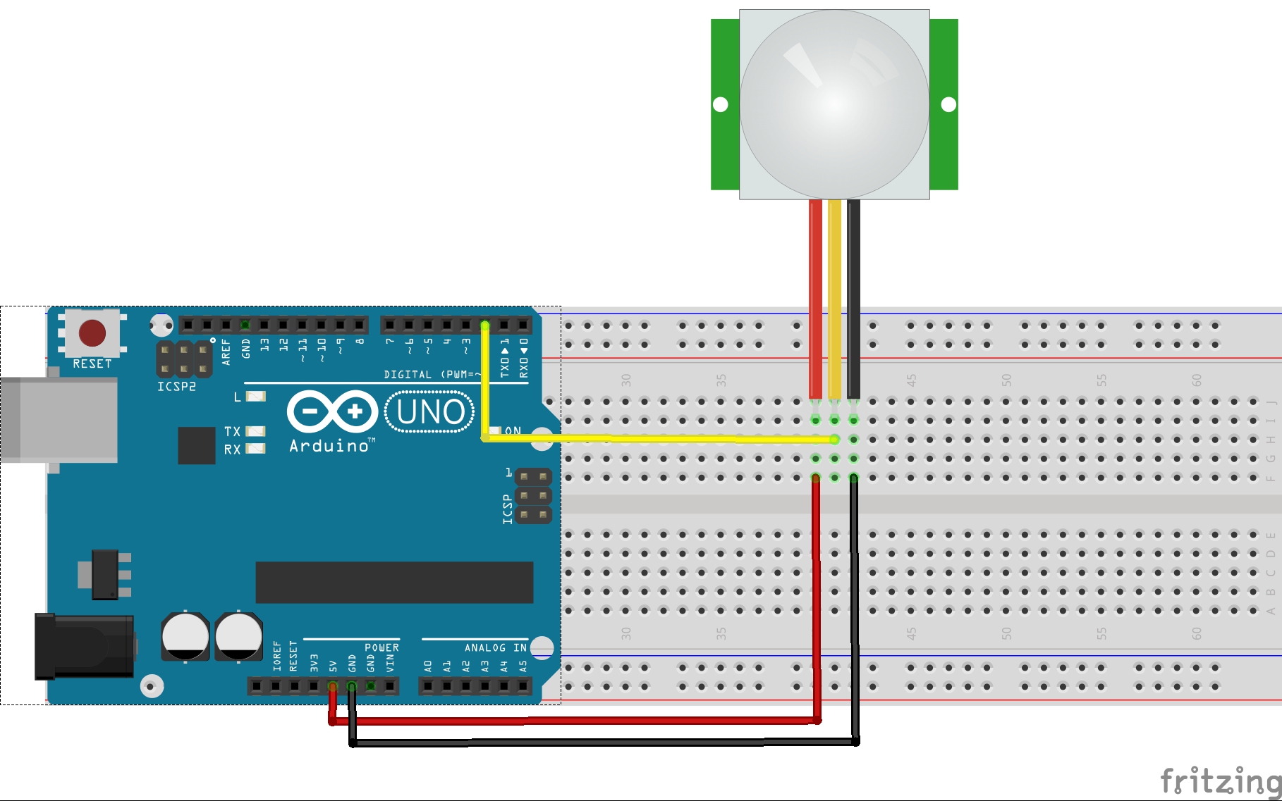
Connecting PIR sensors to a microcontroller is really simple. The PIR acts as a digital output so all you need to do is listen for the pin to flip high (detected) or low (not detected).
Power the PIR with 5V and connect ground to ground. Then connect the output to a digital pin. In this example we’ll use pin 2.
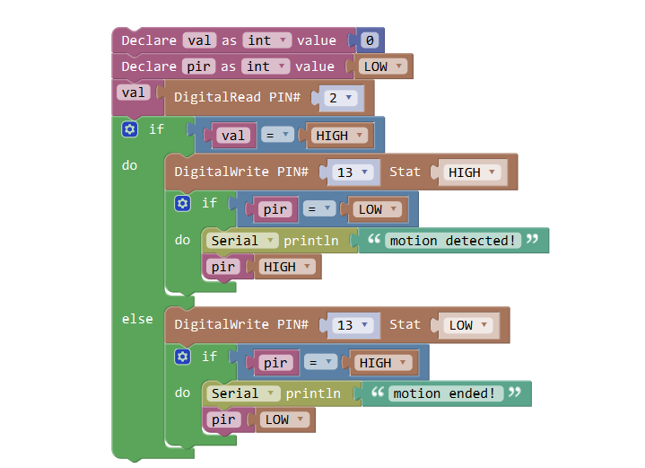
CODE PROGRAM
After above operations are completed, connect the Arduino board to your computer using the USB cable. The green power LED (labelled PWR) should go on.Open the Graphical Programming software Mixly and follow the next operations:
This code just keeps track of whether the input to pin 2 is high or low. It also tracks the state of the pin, so that it prints out a message when motion has started and stopped.
Click Save aftogramming is done. Select the board type and serial port before uploading. For instause a Uno board, just select Arduino/Genuino Uno: if you use a Mega2560, select Arduino/Genuino Mega or Mega2560. 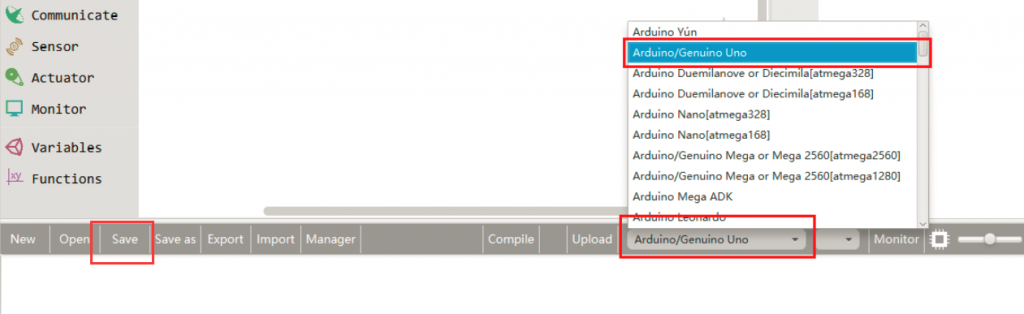
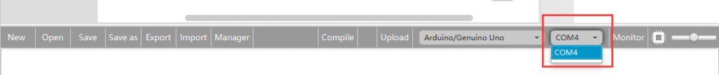
Select the serial device of the Arduino board from the COM menu. This is likely to be COM3 or higher (COM1 and COM2 are usually reserved for hardware serial ports). To find out, you can disconnect your Arduino board and re-open the menu; the entry that disappears should be the Arduino board. Reconnect the board and select that serial port.
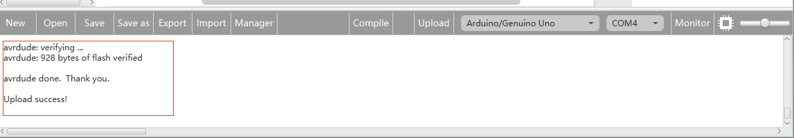
Next,upload the code. If the uploading fails, check and correct the code according to the prompts.


Finally, the staus will change to ‘Upload success!’.

Running Result
A few seconds after the upload finishes, have a look at your Arduino’s pin 13 LED. You can also open your serial monitor, and set the baud rate to 9600 bps, you may see the following:
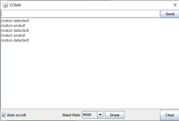
The PIR sensor requires a couple seconds of motion-free activity, while it gets a “snapshot” of it’s viewing area. Try not to move until the pin 13 LED turns off, then wave your hands, jump in the air, go crazy!
You will also notice that there is a delay associated with the motion sensor after each detection. Depending on the sensor, you may be able to adjust this delay.