


I. Objective
II. Parts and Devices
III. Hardware Installation
IV. Software Installation
V. Functional Testing and Verification
V. Troubleshooting

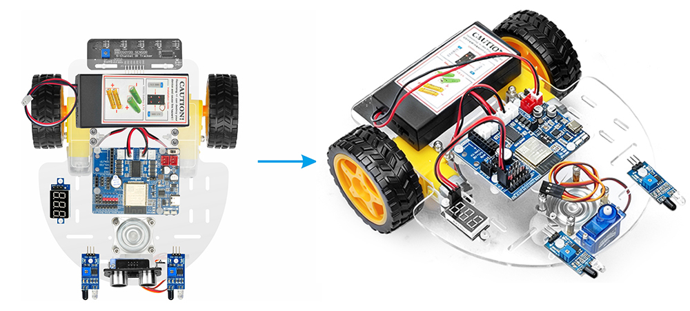
This introductory lesson for the OSOYOO ESPro 2WD (Two-Wheel Drive) Robot Car Kit focuses on the basic mechanical assembly of the robot platform. Its primary goal is to build a simple chassis and integrate the core components needed for subsequent lessons.

OSOYOO ESPro Robot car chassis x1
OSOYOO Wheels x2
OSOYOO DC motors x2
OSOYOO ESPro motor driver board x1
OSOYOO Voltage meter x1
OSOYOO Battery box x1
OSOYOO 3pin female to female jumper wire x1
18650 Batteries (3.7 V) x2
Battery charger x1

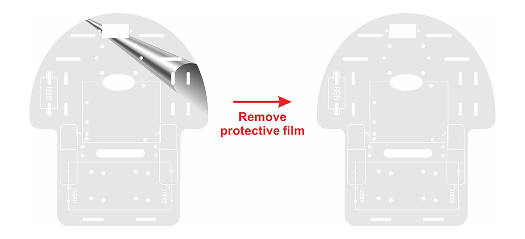
Step (1) Remove the protective film on upper and low car chassis (The chassis has one protective film)
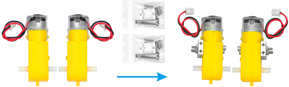
Step (2) Attach the 4 motors using the metal motor holders as shown. (Please ensure the motor orientation is correct before installing the metal motor holders.)
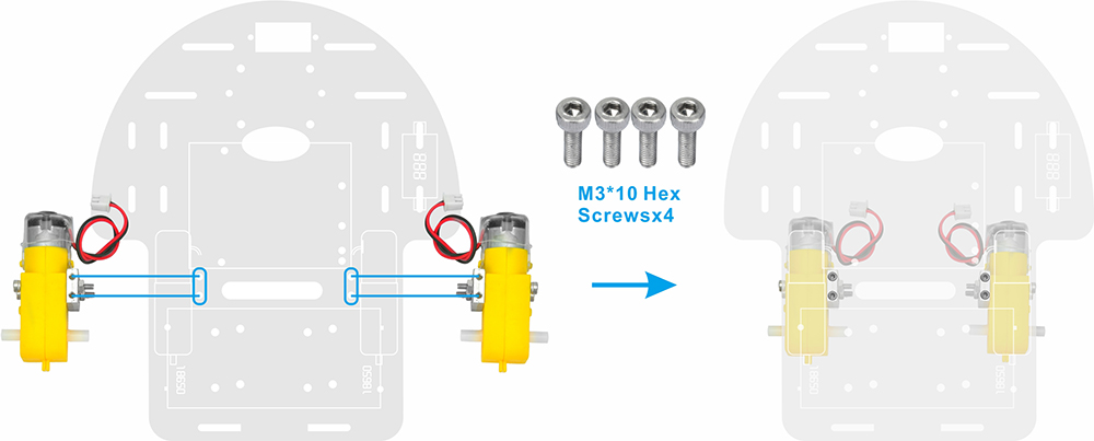
Step (3) Secure the 4 motors to the car chassis using M3*10 hex screws and a hex screwdriver, as shown in the image. (The screws required for this step are included in the metal motor holder package.)
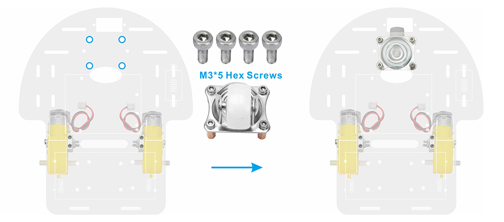
Step (4)Install 4 M3×10 double-pass copper pillars onto the swivel caster using 4 M3×5 hex screws, then attach the swivel caster to the robot car chassis.
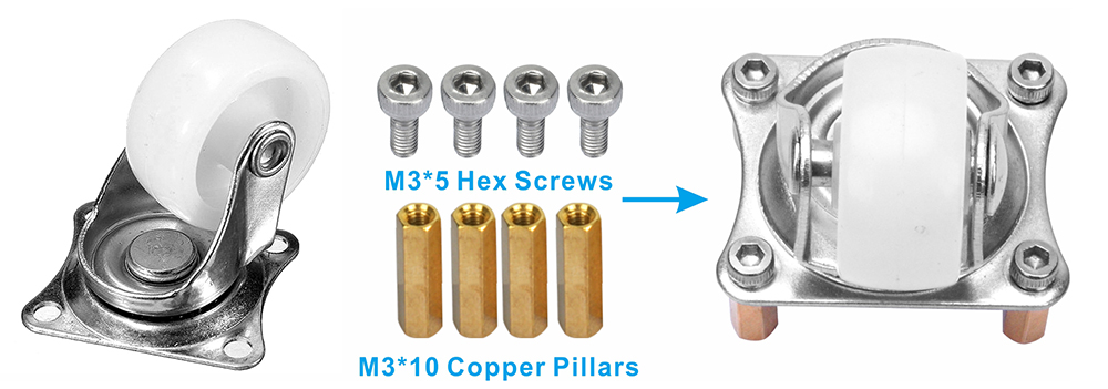
Step (5) Attach the swivel caster to the robot car chassis.
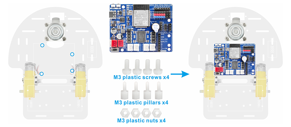
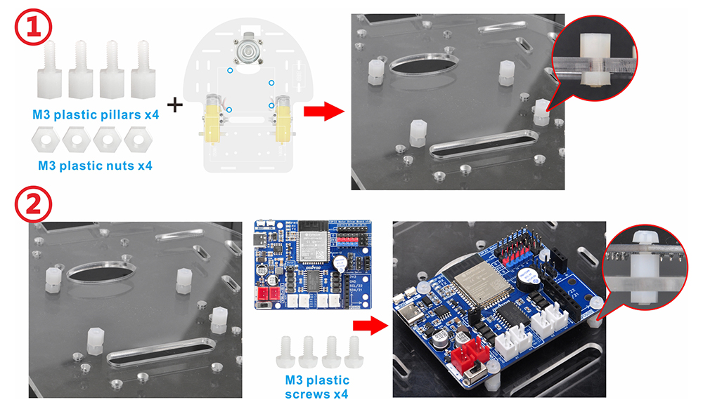
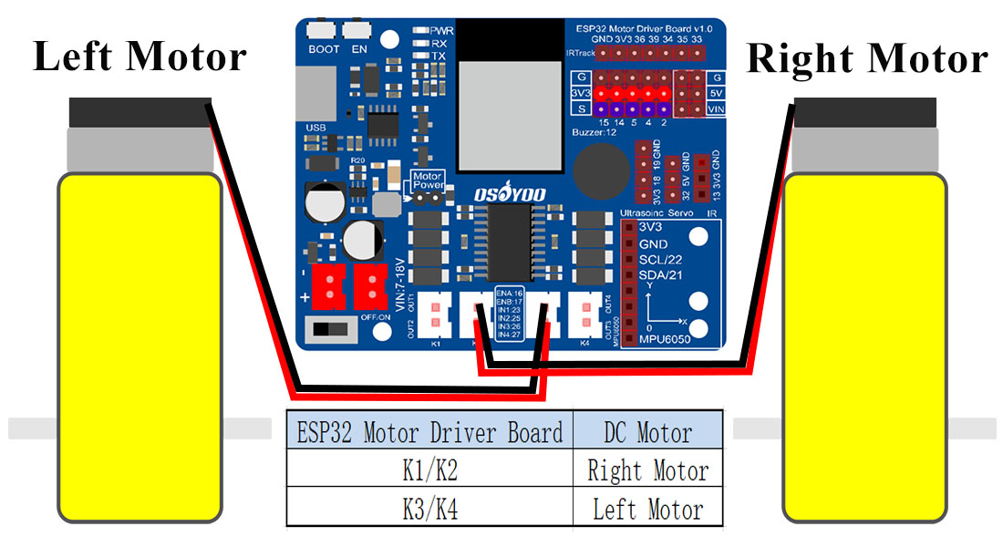
Step (6) Mount the OSOYOO ESPro motor driver board onto the car chassis using 4 M3 plastic screws, plastic pillars, and plastic nuts (It is recommended to install the plastic pillar with the male end facing downward.) . Connect the 2 motors to the K1 and K3 sockets on ESPro motor driver board,as shown in the diagram.
There are two installation modes for plastic pillars:
A. The male end of the plastic pillar faces downward.
B. The male end of the plastic pillar faces upward.
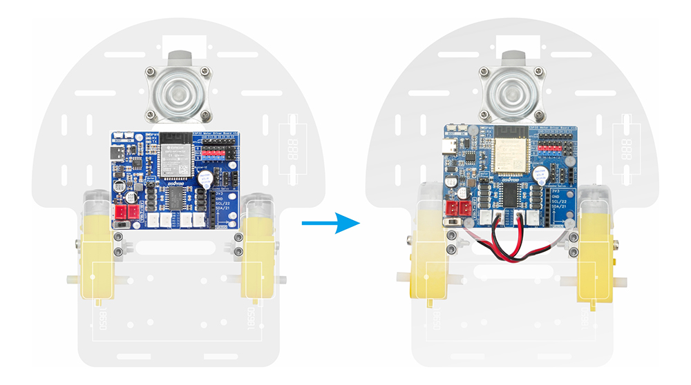
Step (7) Connect the Right motors to K1 sockets and left motors to the K3 on the Espro driver motor driver board, as shown in the diagram.
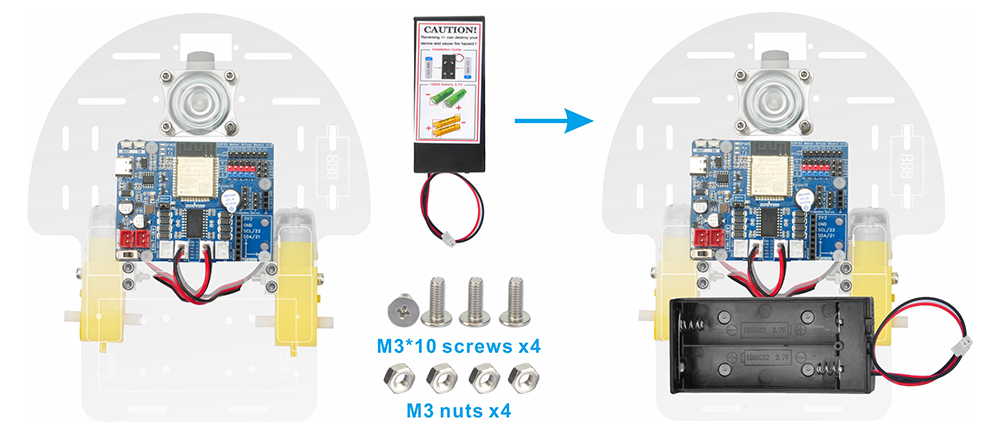
Step (8) Use 4pcs M3*10 screws and M3 nuts to attach the battery box to the designated markings on the car chassis.
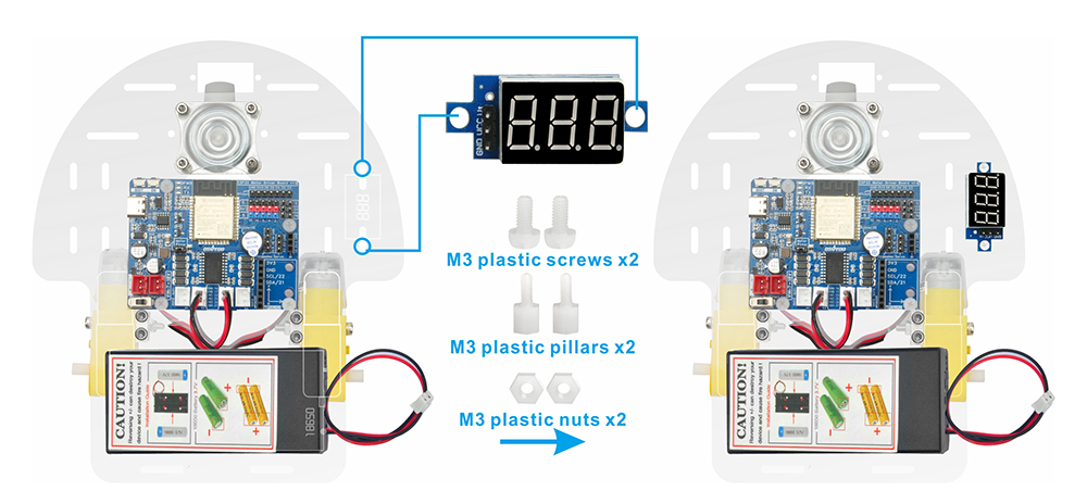
Step (9) Attach the voltage meter to the designated markings on the car chassis using two M3 plastic screws, two M3 plastic pillars, and two M3 plastic nuts.
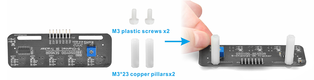
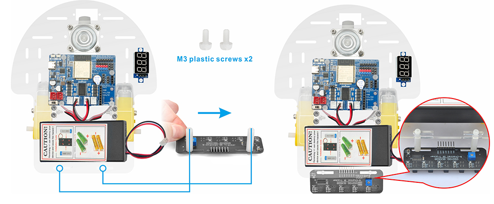
Step (10) Attach the tracking sensor module to the car chassis using 4pcs M3 plastic screws, 2pcs M3x23 plastic pillars.
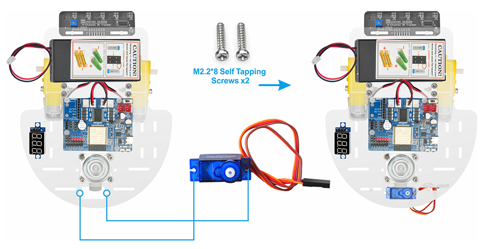
Step (11) Using two M2.2*8 self-tapping screws, mount the servo motor at the front of the car chassis.
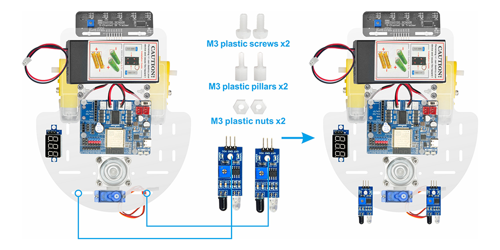
Step (12) Attach two IR distance sensors to the front of the car chassis using two M3 plastic screws, M3 plastic pillars, and M3 plastic nuts.
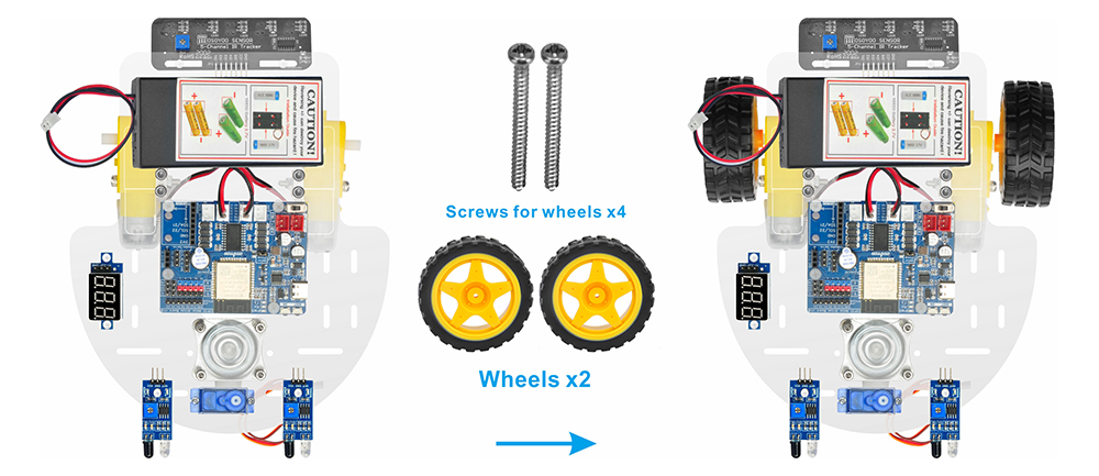
Step (13) Install 2 wheels onto the motors with 2pcs M2.2×22 screws or M2.5X20 or M2.6×20 Self-tapping screws.
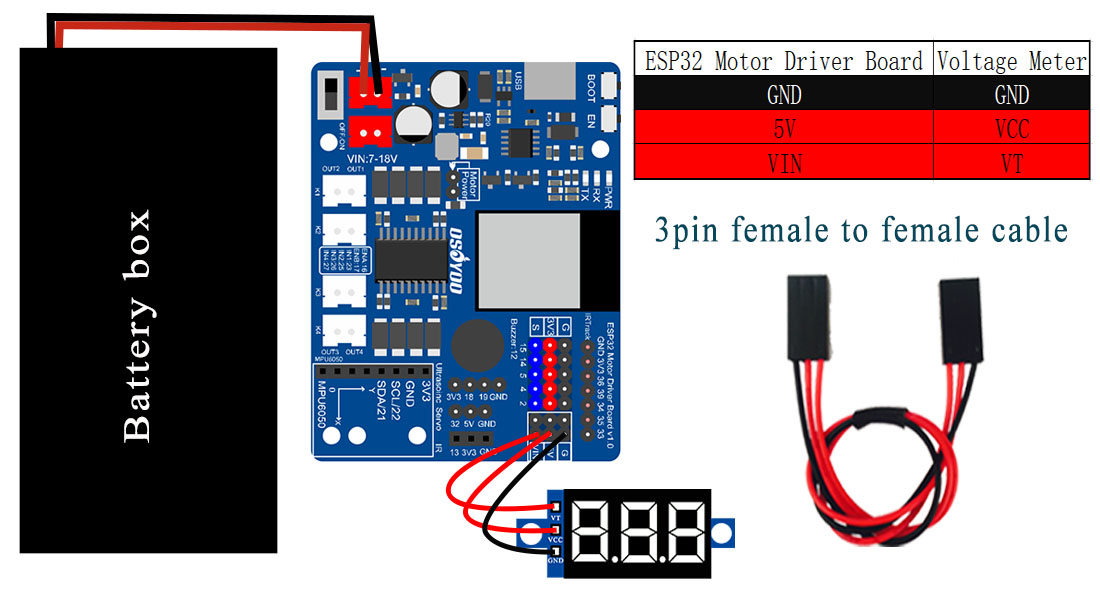
Step (14)
Connect the voltage meter to the OSOYOO ESPro motor driver board using a 3-pin female-to-female jumper wire as shown in the connection diagram.
Connect the battery box to the VIN socket of the OSOYOO ESPro motor driver board according to the diagram.

Step 1: Install latest Arduino IDE (If you have Arduino IDE version after 1.1.16, please skip this step). Download Arduino IDE from https://www.arduino.cc/en/Main/Software?setlang=en , then install the software.
Step 2: Download https://osoyoo.com/driver/espro-2wd-car/espro-lesson1-basic.zip, unzip the download zip file espro-lesson1-basic.zip, you will see a folder called espro-lesson1-basic.zip.
Step 3: Connect ESPro motor driver board to PC with USB cable, Open Arduino IDE -> click file -> click Open -> choose code “espro-lesson1-basic.ino” in lesson1 folder, load the code into arduino.
Step 4: Install ESPro motor driver board Board: Connect the ESPro motor driver board to Desktop or Laptop computer with Type-C USB cable.
In Arduino Setting->Preference, please copy and past following link into Board Manager Url field:
https://raw.githubusercontent.com/espressif/arduino-esp32/gh-pages/package_esp32_index.json
Step 5: After you select OK, then in Tool->Board->board Manager, Search ESP32 and Add ESP32 into Board Manager.
Then in Tool->Board, select esp32 ->ESP32 Dev Module,
Last select correct port which matches ESP32 board,upload the sketch to the board.

Disconnect the ESP32 motor driver board from the PC and insert batteries into the battery box. Place the car on the ground and turn on the switches on both the OSOYOO ESP32 motor driver board and the battery box (if installed).
The car should perform the following sequence:
Forward → Backward → Left Turn → Right Turn ,and then stop.