はじめに
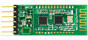
HC-02 Bluetoothシリアル通信モジュールは、Bluetooth V2.0 Bluetoothプロトコルデータ伝送モジュールに基づいており、高安定性、超低消費電力、工業グレードBluetoothデータ伝送モジュールです。
ユーザーは複雑な無線通信設定や伝送アルゴリズムを気にする必要はありません。TTLシリアルポートを通じてデバイスに接続するだけで済みます。HC-02スレーブモジュールに電源を供給すれば、モバイルフォンと接続してデータ伝送を行うことができます。さらに、HC-05またはHC-06ホストと
(ペアリングコード、デフォルトは1234)接続することができ、従来のシリアルケーブルに代わって使用でき、配線作業を省力化し、
非常に柔軟に使用できます。
iPhoneやiPadを使用してArduinoプロジェクトを制御する必要がある場合、6ピンベースボード付きhc-02 4.0 bleスレーブモジュールが良い選択かもしれません。iOS7.0以降に完全対応しています。Android 4.3以降にも対応しています。
ご注意:
Android OSのバージョンが4.3未満の場合、対応していません。
このモジュールはBluetooth 4.0 bleモードとBluetooth 2.0モードをサポートしています。
Bluetoothにあまり詳しくない場合は、こちらからBluetoothに関する詳細情報を得ることができます。
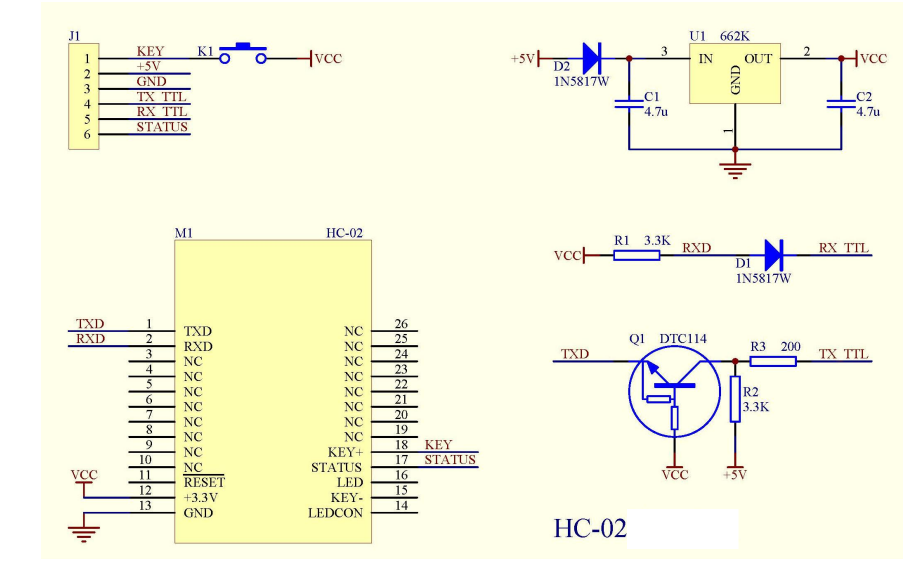
HC-02の回路図
特徴
| モデル |
HC-02 |
モジュールサイズ |
27*13mm |
| 動作バンド |
2.4G |
空中レート |
2Mbps |
| 通信インターフェース |
UART3.3V TTL |
アンテナインターフェース |
内蔵PCBアンテナ |
| 動作電圧 |
3.0~3.6V |
通信電流 |
30mA |
| ボーレート |
1200~115200bps |
受信感度 |
-85dBm@2Mbps |
| 通信レベル |
3.3V |
動作湿度 |
10%~90% |
| 送信出力 |
6dBm (最大) |
保管温度 |
-40 C ~+85 C |
| 参考距離 |
10m |
動作温度 |
-25 C ~75 C |
- コアモジュールにはHC-08を使用し、モジュールインターフェースからのリードにはVCC、GND、TXD、RXD、LEDステータス出力ピンが含まれます。
- LEDはBluetooth接続状態を示し、Bluetooth接続可能時に点滅し、Bluetooth接続およびポートオープン時に点灯します。バックプレート
- 3.3V LDO入力電圧3.6 6V、入力電圧は7V以上を禁止
- インターフェースレベル3.3V、各種MCU(51、AVR、PIC、ARM、MSP430等)に直接接続可能、5V MCUにも直接接続可能。
- 有効距離10メートル、10メートル以上も可能ですが、この距離の接続品質を保証するものではありません。
- ペアリング後、全二重シリアルポートとして使用する場合、Bluetoothプロトコルについて何も知る必要はなく、8データビット、1ストップビット、パリティなしの通信形式のみをサポートしています。これは最も一般的に使用される通信形式であり、他の形式はサポートしていません。
- コンパクト(3.57cm * 1.52cm)、工場出荷時のチップ製造により配置品質を保証。透明熱収縮チューブセット付き、防塵で美観、静電気防止。
ピン構成
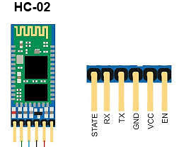
| ピン番号 |
ピン名 |
説明 |
| 1 |
Enable / Key |
このピンはデータモード(ロー設定)とATコマンドモード(ハイ設定)の切り替えに使用されます。デフォルトではデータモードです |
| 2 |
Vcc |
モジュールの電源供給。+5V/+3.3V電源電圧に接続 |
| 3 |
Ground |
モジュールのグラウンドピン、システムグラウンドに接続。 |
| 4 |
TX – 送信機 |
シリアルデータの送信。Bluetooth経由で受信したものはすべて、このピンからシリアルデータとして出力されます。 |
| 5 |
RX – 受信機 |
シリアルデータの受信。このピンに与えられたシリアルデータはすべて、Bluetooth経由でブロードキャストされます |
| 6 |
State |
ステートピンはオンボードLEDに接続されており、Bluetoothが正常に動作しているかを確認するフィードバックとして使用できます。 |
| 7 |
LED |
モジュールの状態を示します
- 2秒ごとに1回点滅: モジュールがコマンドモードに入った
- 繰り返し点滅: データモードで接続待ち
- 1秒ごとに2回点滅: データモードで接続成功
|
HC-02 Bluetoothモジュールの使用場所
HC-02は、プロジェクトに双方向(全二重)無線機能を追加できる非常に優れたモジュールです。このモジュールを使用して、Arduino用などの2つのマイコン間で通信したり、PhoneやLaptopなどのBluetooth機能を備えたデバイスと通信したりできます。すでに多くのAndroidアプリケーションが利用可能で、このプロセスをはるかに簡単にします。iPhoneにも完全対応しています。このモジュールはUSARTで9600ボーのレートで通信するため、USARTをサポートするマイコンとのインターフェースは簡単です。コマンドモードを使用してモジュールのデフォルト値を設定することもできます。したがって、コンピュータや携帯電話からマイコンにデータを転送したり、その逆を行ったりする無線モジュールをお探しの場合、このモジュールが適しているかもしれません。
ただし、このモジュールで写真や音楽などのマルチメディアを転送することを期待しないでください。そのためにはCSR8645モジュールを検討する必要があります。
HC-02 Bluetoothモジュールの使用方法
HC-02には2つの動作モードがあります。1つは他のBluetoothデバイスとの間でデータの送受信ができるデータモード、もう1つはデフォルトデバイス設定を変更できるATコマンドモードです。ピン説明で説明したように、キーピンを使用してこれらの2つのモードのいずれかでデバイスを操作できます。
HC-02モジュールをマイコンとペアリングするのは非常に簡単です。シリアルポートプロトコル(SPP)を使用して動作するためです。モジュールに+5V/+3.3Vで電源を供給し、下図のようにモジュールのRxピンをMCUのTxに接続し、モジュールのTxピンをMCUのRxに接続するだけです
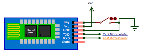
電源投入時、キーピンをグラウンドに接続するとコマンドモードに入り、フリーのままにするとデフォルトでデータモードに入ります。モジュールに電源が供給されるとすぐに、「HC-02」としてBluetoothデバイスを発見できるはずなので、デフォルトパスワード1234を使用して接続し、通信を開始できます。
動作原理
MCUとの接続

他のBluetoothモジュールとの接続

HC-06がホスト、HC-02がスレーブ、ペアリングコードが一致(デフォルトは1234)、ボーレートが同じであれば、電源投入時に自動接続できます。初回接続後、HC-06ホストは自動的にペアリング対象を記憶します。他のモジュールに接続したい場合は、まずHC-06ホストのペアリングメモリをクリアする必要があります。スレーブ側にはペアリングメモリはありません。
Android携帯電話との接続
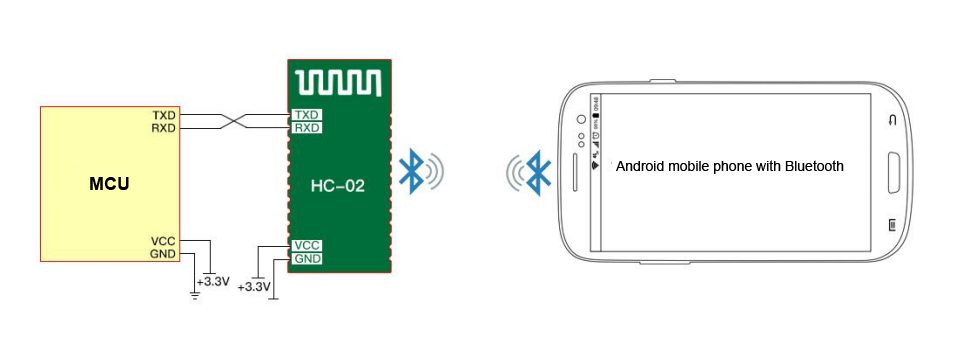
HC-02はBluetooth経由でAndroid携帯電話に接続でき、AndroidではAndroidシリアルアシスタントソフトウェアを使用できます。
iPhoneとの接続
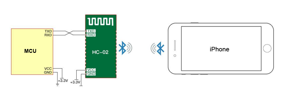
HC-02はiPhone 4S以降のiPhoneに接続できます。通信テストにはBLEシリアルアシスタントソフトウェアのダウンロードとインストールが必要です。
注意:
独自サービスUUID: 49535343-FE7D-4AE5-8FA9-9FAFD205E455
TX UUID: 49535343-1 E4D-4BD9-BA61-23C647249616
RX UUID: 49535343-8841-43F4-A8D4-ECBE34729BB3
PCとの接続

HC-02はHC-06-USB Bluetooth仮想シリアルポート経由でコンピュータに接続できます。
HC-02はコンピュータのBluetoothデバイスに接続して通信できます。
アプリケーション
1. 2つのマイコン間の無線通信
2. ノートPC、デスクトップ、携帯電話との通信
3. データロギングアプリケーション
4. 消費者向けアプリケーション
5. 無線ロボット
6. ホームオートメーション
ATコマンド
ATコマンドモードへの方法: モジュールに電源を供給し、ペアリングが不要な場合、
ATモードに入ります。コマンドの間隔は約1秒です。
デフォルトパラメータ: ボーレート:9600N81、ID: linvor、パスワード:1234
1. 通信テスト
送信: AT (1秒ごとに送信してください)
戻り: OK
2. Bluetoothシリアルボーレートのリセット
送信: AT+BAUD1
戻り: OK1200
送信: AT+BAUD2
戻り: OK2400
……
1———1200
2———2400
3———4800
4———9600 (デフォルト)
5———19200
6———38400
7———57600
8———115200
9———230400
A———460800
B———921600
C———1382400
PCは115200より高いボーレートをサポートできません。解決策は: プログラミングを通じてMCUがより高いボーレート
(115200より大きい)を持ち、AT
コマンドを通じてボーレートを低レベルにリセットすることです。
ATコマンドによるボーレートリセットは、電源が切られても
次回のために保持されます。
3. Bluetooth名のリセット
送信: AT+NAMEname
戻り: OKname
例:
送信: AT+NAMEosoyoo
戻り: OKname
このときBluetooth名は”osoyoo”に変更されます。
4. Bluetoothペアリングパスワードの変更
送信: AT+PINxxxx
戻り: OKsetPIN
詳細情報はATコマンドについてこちらのリンクを確認してください。
サンプルATコマンドプロジェクト
Arduino UNOボードを使用してHC-02モジュールにATコマンドを送信し、Bluetooth名を変更する
目的: 多くの学校のロボット教室では、多くの学生が同じBluetooth名「HC-02」の複数のHC-02モジュールを使用しており、これにより学生のプロジェクト間で多くの競合が発生します。そのため、各学生のHC-02モジュールを他の人と競合しない一意の名前に変更する必要があります。
Arduinoボードを使用してHC-02にATコマンドを送信し、その名前を変更する方法は以下の通りです:
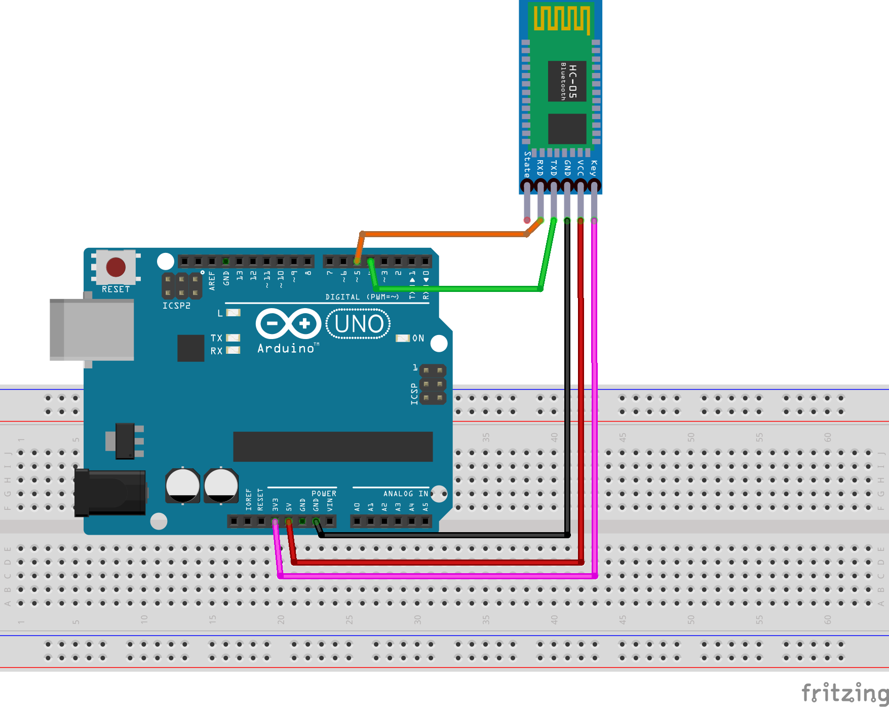
1)配線接続
-
HC-02 TX → Arduino D4 (SoftwareSerial RX)
-
HC-02 RX ← Arduino D5 (SoftwareSerial TX)
-
HC-02 VCC → 5V
-
HC-02 GND → GND
-
HC-02 KEY→ HIGH (3.3V or 5V)
2)以下のリンクからArduino ATコマンドスケッチをダウンロード:
https://osoyoo.com/driver/2wd/hc02.zip
上記ファイルを解凍すると、「hc02」というフォルダが表示されます。そのフォルダに入り、hc02.inoファイルをダブルクリックしてArduino IDEで開いてください。
3)シリアルモニターでATコマンドをテスト
hc02.inoコードをArduinoにアップロードした後、Arduino IDEシリアルモニターを開き、ボーレートを9600に設定し、ラインモードをNo Line Endingに設定してください:
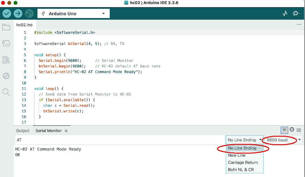
ATコマンドをテストするには、出力フィールドにATと入力してEnterキーを押してください。シリアルモニターにOKが表示されるはずです(上記の画像を参照)。OKが表示されない場合は、ステップ1〜3を再確認してください。
4) 이제 AT コマンドを使用して HC-02 Bluetooth モジュールを変更できます。
フォーマットは AT+NAMEnewname です
例えば、HC-02モジュール名をosoyoo2025に変更したい場合、シリアルモニターに以下のATコマンドを入力してください:
AT+NAMEosoyoo2025
Enterキーを押すと、シリアルモニターに以下のように応答します:
OKsetname
これは、Bluetoothモジュールの新しい名前がosoyoo2025に変更されたことを意味します


this is strange. why does the label say hc-01 and yet your website says hc-02; at-command link does not work
the HC-02 is a sub-category of HC-01 serial bluetooth module. Which HC-02 AT command doesn’t work? Can you give us some more detail so that we can help you? If possible, copy the error message to this comments area.
link gives: The master branch of osoyoo-datasheet does not contain the path bluetooth/HC-05_english_AT_commamd_set.pdf.
I tried plugging in module to arduino got no bluetooth connection
here is the link: https://github.com/osoyoo/osoyoo-datasheet/blob/master/bluetooth/HC-05%20english%20AT%20commamd%20set.pdf
what is pin 34 as mentioned in the first page
Pin 34 is the HC-02 internal pins, you don’t need to care about the detail. You don’t even need to read this AT-Command tutorial because HC-02 has already set default baud rate 9600 by factory . If you don’t want to change baud rate, don’t use any AT command.
You only need to know that HC-02 TX/RX will connect to the RX/TX in Arduino. Then you can set Arduino Serial baud rate 9600 and talk to cell phone APP through HC-02(suppose your cell phone has paired with HC-02) with Arduino Serial.read, Serial.write functions.
is the tx and rx of hc module connected to the tx and rx of arduino
No. You are totally wrong. Serial protocol requires one Device’s TX connects to another device’s RX pin.
Please read our tutorial carefully “….Simply power the module with +5V/+3.3V and connect the Rx pin of the module to the Tx of MCU and Tx pin of module to Rx of MCU….”, also see following circuit graph in the tutorial:

the tx and rx of the mcu represents tx and rx of arduino? or am i wrong? can i get diagram of shield for 2.1 arduino car
if you want to use HC-02 to control V2.1 car, you don’t need to care about how the TX/RX connected. You simply insert the HC-02 into the HC-02 slot in the wifi shield as following:

Make sure the HC-02 TX pin is into the BLE-TX hole and HC-02 RX is in the BLE-RX hole same as above picture.
You also need to use a jumper cap to connect the D4 to B_TX and D5 to B_RX (see the two little red line in above picture). this will make the HC-02 module connect to Arduino software Serial in D4/D5 pin.
then run the code https://osoyoo.com/driver/v2smartcar-lesson7.zip
The code use D4/D5 pin to exchange data with HC-02. HC-02 is a bluetooth bridge between your cell phone APP and Arduino.
For more information about bluetooth APP control V2.1 car through HC-02 module, please read following tutorial:
https://osoyoo.com/2020/05/12/osoyoo-v2-robot-car-lesson-7-imitation-driving-with-bluetooth-app-2/
can i see how the matching connector connects to arduino
We don’t quite understand what is your purpose to ask “how the matching connector connects to arduino?”. I guess your concern might be of following two reasons:
1)You want to use HC-02 to connect Arduino to do some your own Bluetooth communication project? If this is your case, you can connect HC-02 to any digital pin of Arduino by jumper wire. For example, you can connect HC-02 TX pin to Arduino D3 and HC-02 RX pin to Arduino D2, then you need to use Arduino SoftSerial functions to define D3 as SoftRX and D2 as SoftTX by following command:
SoftwareSerial BLTSerial(3, 2);
then you can use BLTSerial.read() or BLTSerial.write() to receiver or send data to remote bluetooth device.
or
2)If you are talking about our V2.1 car lesson 7 bluetooth project. The HC-02 is inserted into Wifi Shield bluetooth slot (see following):

In above project, HC-02 TX is automatically connected D4 and HC-02 RX is automatically connected to D5. So you can read our sample code line 16:
SoftwareSerial BLTSerial(4, 5);
In above code, you can see Arduino D4 is Software RX and must be connected to HC-02 TX pin. The same logic, Arduino D5 is Soft TX and must be connected to Hc-02 RX pin.
lesson 7 code is very good sample software to understand HC-02 bluetooth module communication through Soft Serial port.
If you don’t understand what are Serial Communication and Software Serial communication in Arduino, we suggest you google and read some article to understand the concept first before reading our code, otherwise you might be confused.
I am thinking about using 1). Can you give me example pin to pin diagram and sample code
also what is key and status of hc-02 used for
You don’t need to care about key and status pin. They are used for flashing the firmware of HC-02, you won’t use them in programming. You can leave them empty(not connecting to anything).
Here is a simple example of HC-02 talking to Arduino:
https://osoyoo.com/2018/08/23/hc-02/
Please read above tutorial and sample code carefully. The code receive text message from cell phone APP, APP send bluetooth message to Arduino through HC-02. When the message is “1” , Arduino turn on LED in D13, when message is 0, Arduino turn off D13 LED.
It is quite straight forward.
Hope this helps.