正規オンライン販売店:

Buy from USA Buy from UK Buy from DE Buy from IT Buy from FR Buy from ES ここでご購入を!

Lesson 3では、ADCアナログ入力とPWMアナログ出力の概念を学びました。今回は、新しいアナログ入力デバイスとPWM出力デバイスを使用します。

このレッスンでは、ポテンショメータ(可変抵抗器)からアナログ信号をPico ADCピン(GP28)を介して読み取る方法を紹介します。また、PWM信号を生成できるGP16にサーボモータを接続します。ポテンショメータを回転させると、サーボがアームを回転させます。

必要なもの:

Raspberry Pi PicoボードとmicroUSBケーブル
Thonny Python IDEを実行するためのコンピュータ
ブレッドボード×1
ポテンショメータ×1
サーボモータ×1

上の回路図では、次のようになります:

サーボの赤いワイヤーはPicoのVbusピン(5V)に接続されます。
サーボの茶色のワイヤーはPicoのGNDに接続されます。
サーボの黄色いワイヤーはPicoのPWMピン(GP16)に接続されます。
ポテンショメータのGNDはPicoのGNDに接続されます。
ポテンショメータのVCCはPicoの3.3Vに接続されます。
ポテンショメータの中央のピンはPico ADCピン(GP28)に接続されます。

レッスン5のPythonコードは、https://osoyoo.com/driver/pico/lesson5/pico-lesson5.pyからダウンロードできます。

Thonnyを使用してpico-lesson5.pyを開き、後でPicoにロードできます。

以下がコメント付きの全コードです:

from machine import Pin, PWM, ADC #import libraries for Pin, PWM, ADC
from time import sleep

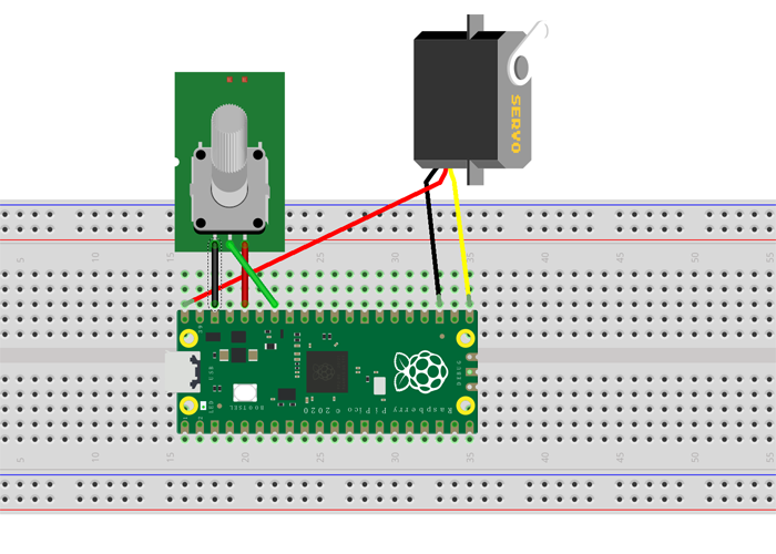
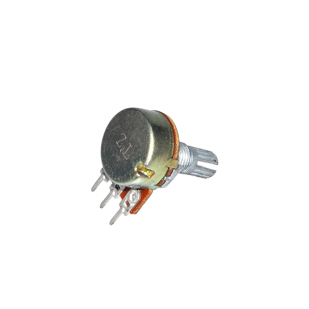
adc = ADC(Pin(28))      #set Potentiometer analog input from GP28 pin
    
servoPin = PWM(Pin(16)) #set servo pwm output to GP16 pin
servoPin.freq(50)       #set servo frequency 50

def servo(degrees):     #rotate servo arm to degrees position
    # limit degrees beteen 0 and 180
    if degrees > 180: degrees=180
    if degrees < 0: degrees=0
    # set max and min duty
    maxDuty=9000
    minDuty=1000
    # new duty is between min and max duty in proportion to its value
    newDuty=minDuty+(maxDuty-minDuty)*(degrees/180)
    # servo PWM value is set
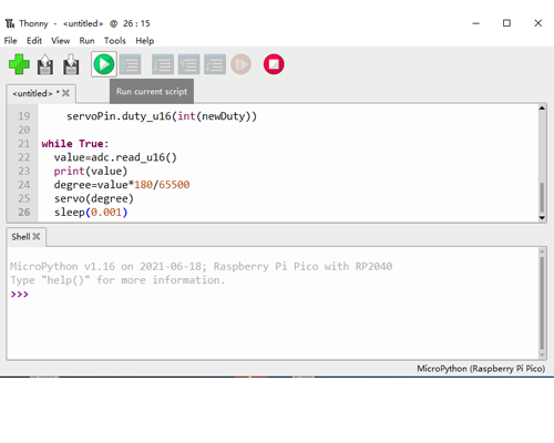
    servoPin.duty_u16(int(newDuty))

while True:
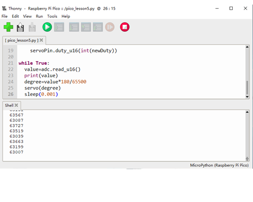
  value=adc.read_u16()   #read Potentiometer value
  print(value)
  degree=value*180/65500 #convert Potentiometer value to a servo position angle
  servo(degree)         #rotate servo to that angle     
  sleep(0.001)

Step 1: PicoボードをPCのUSBポートの1つに接続します。

Step 2: Thonnyソフトウェアをインストールしていない場合、またはThonny IDEの使用方法を知らない場合は、レッスン1を読んでください。

Step 3: Thonny Python IDEを開き、実行をクリックして、Raspberry Pi PicoのMicroPythonをインタープリタとして選択してください。

また、Picoボードが接続されているCOMポートを選択してください。

その後、設定を保存するためにOKをクリックしてください。

Step 4: Pythonコードを以下のようにThonnyウィンドウにコピーしてください。

Step 5: 小さな►ボタンをクリックすると、次の写真に示すように保存ダイアログボックスが表示されます。

宛先としてRaspberry Pi Picoを選択してください。

Step 6: ファイル名をpico-lesson5.pyとして設定し、OKをクリックしてください。

Step 7: 再度小さな►ボタンをクリックしてPythonコードを実行してください。

これで、ポテンショメータを回転させることができ、サーボアームがそれに応じて回転することが確認できます。

操作が完了したら、Ctrl+Cを押してコマンドを終了してください。

SKU:2021005900のパーツについてもっと学びましょう。


No. 画像 商品名 Link
1 Raspberry Piピコボード https://osoyoo.store/products/raspberry-pi-pico-flexible-microcontroller-board-based-on-the-raspberry-pi-rp2040-dual-core-arm-cortex-m0-processor-1-pc?variant=39875307864175
2 サーボモーター https://osoyoo.store/products/micro-servo-sg90-blue-for-arduino-v2-0-robot-carmodel-lacc200610?variant=31648847560815
3 赤外線センサーモジュール https://osoyoo.store/products/hc-sr501-pir-motion-sensor-for-arduino?variant=31957812838511
4 RFID モジュールとカード https://osoyoo.store/products/osoyoo-rfid-module?variant=31970646130799
5 押しボタンと帽子 https://osoyoo.store/products/push-button-and-hats-5pcs?variant=39879253131375
6 LED(白×6、赤×6、黄×6、緑×6) https://osoyoo.store/products/led-packs-for-arduino?variant=31957816442991
7 サーボモーター https://osoyoo.store/products/sg90-micro-servo-for-arduino-raspberry-pi-robot?variant=31957821096047
8 ピエゾブザーモジュール https://osoyoo.store/products/piezo-buzzer-module-1pcs?variant=39879251656815
9 I2C LCDディスプレイ(16×2) https://osoyoo.store/products/i2c-lcd1602-display?variant=39875437101167
10 プラスドライバー https://osoyoo.store/products/phillips-screwdriver?variant=31930635780207https://osoyoo.store/products/single-channel-relay-module-for-arduino-raspberry-pi?variant=31955954401391
11 ブレッドボード https://osoyoo.store/products/solderless-prototype-breadboard-1pcs?variant=39879255457903
12 ポテンショメータ (10KΩ可変抵抗器) https://osoyoo.store/products/potentionmeter-10k-adjustable-resistor-3pcs?variant=39879281016943
13 40Pin M から M へのジャンパー線 https://osoyoo.store/products/40pin-m-to-m-jumper-wires?variant=39879256539247
14 20Pin M – F ジャンパー線 15cm https://osoyoo.store/products/20pin-15cm-female-to-female-cable?variant=31930663305327