注:すべてのOsoyoo製品は、arduinoコンテンツと完全に互換性のある第三者ボードです。
コンテンツ
- はじめに
- 準備
- 8×8LEDマトリクスについて
- 使用例
はじめに
LEDディスプレイは、共通アノードの行と共通カソードの列、またはその逆に配置されたLEDのマトリックスとしてパッケージされることが多い。最近のLEDサインボードの多くは、コントローラー付きの様々なタイプのマトリックスボードを使用しています。このレッスンでは、単色8×8 LEDマトリクスをArduinでインターフェイスし、いくつかの文字を表示して、その魅力を最初から体験します。
準備
ハードウェア
- Osoyoo UNOボード (Arduino UNO rev.3と完全互換) x 1
- 8×8 LEDマトリクス x 1
- 10kΩポテンショメーター x2
- M/Mジャンパー
- ブレッドボード x 2
- USBケーブル x 1
- PC x 1
ソフトウェア
- Arduino IDE (version 1.6.4+)
8×8 LEDマトリクスについて
8×8LEDマトリックスLEDディスプレイは、低電圧スキャンにより、省電力、長寿命、低コスト、高輝度、広視野角、長視野距離、防水性などの長所があります。異なるアプリケーションのニーズを満たすことができるため、幅広い発展の見通しを持っています。
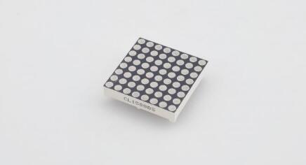
8×8マトリクスは64個のドットまたはピクセルで構成される。各ピクセルにはLEDがあり、これらのLEDは合計16ピンに接続されている。
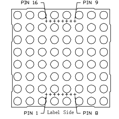
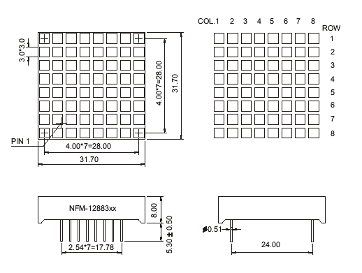
一般に、ドット・マトリクスにはコモンカソードとコモンアノードの2種類がある。外観はほとんど同じです。しかし、通常は見分けやすいようにラベルが貼られている。ラベルの末尾がAXのものがコモンカソードドットマトリックスで、BXのものがコモンアノードドットマトリックスです。どのように見えるかは下の図を見てほしい。つまり、ピンはマトリックスの両端に配置されている。一方の端(通常はラベル側)のピンは左から右に1-8、反対側の端は右から左に9-16となっています。
下図でピン配置を確認できる。
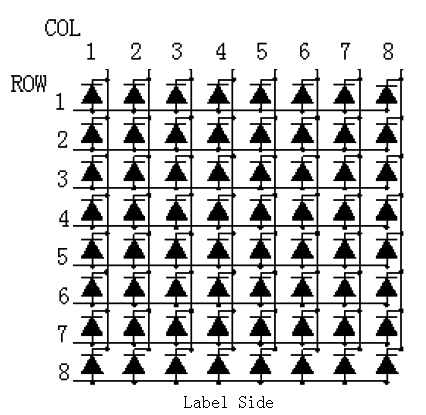
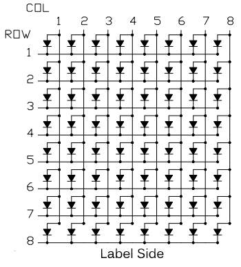
下図は内部構造である。コモンアノード・ドットマトリクスの場合、ROWがLEDのアノード、COLがカソードになりますが、コモンカソードの場合は逆になります。ただし、どちらのタイプも、列はドットマトリックスの13、3、4、10、6、11、15、16番ピンで、行は9、14、8、12、1、7、2、5番ピンである。
左上隅の最初のLEDを点灯させる場合、コモンアノードドットマトリックスでは9番ピンをハイレベル、13番ピンをローレベルに設定する必要があります。コモンカソードドットマトリックスでは、13番ピンをローレベル、行9,14,8,12,1,7,2,5番ピンをハイレベルに設定します。コモンアノードの場合は、13番ピンをハイレベルにし、それらの行をローレベルにします。下図を参照してください。
上の図に基づき、ピン接続のマトリックスを示します:
| Matrix pin no. |
Row |
Column |
Arduin pin number |
| 1 |
5 |
– |
13 |
| 2 |
7 |
– |
12 |
| 3 |
– |
2 |
11 |
| 4 |
– |
3 |
10 |
| 5 |
8 |
– |
16 (analog pin 2) |
| 6 |
– |
5 |
17 (analog pin 3) |
| 7 |
6 |
– |
18 (analog pin 4) |
| 8 |
3 |
– |
19 (analog pin 5) |
| 9 |
1 |
– |
2 |
| 10 |
– |
4 |
3 |
| 11 |
– |
6 |
4 |
| 12 |
4 |
– |
5 |
| 13 |
– |
1 |
6 |
| 14 |
2 |
– |
7 |
| 15 |
– |
7 |
8 |
| 16 |
– |
8 |
9 |
寸法は以下の通り:
注意:
行と列をマイコンのどのピンに接続するかは問題ではない。配線が最も簡単になるようにピンを接続します。電源の組み合わせは64通りあり、手作業で行うのは事実上不可能だ。そのため、Arduinは8×8マトリックスとインターフェイスしています。
例
8×8マトリックスのLEDを点灯させる
上記のサブタイトルの通り、マトリックス上のLEDを点灯させる方法を紹介します。
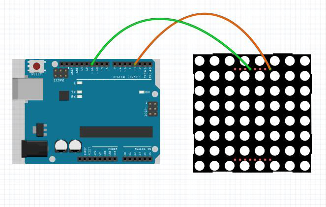
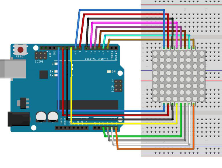
回路図
左上の最初のLEDを点灯させるには、コモンアノードドットマトリックスの場合、9番ピンをハイレベル、13番ピンをローレベルに設定する必要があります。コモンカソードの場合は、13番ピンをハイレベル、9番ピンをローレベルに設定します。
スケッチのアップロード
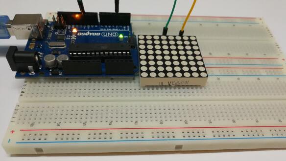
上記の操作が完了したら、USBケーブルを使ってボードをコンピューターに接続します。緑色の電源LED(PWRと表示)が点灯するはずです。
プログラムのコード化
以下のコード例 をプログラムにコピーしてください。
int pin3=3; //Connect the matrix pin 9 to Uno pin 3
int pin11=11;//Connect the matrix pin 13 to Uno pin 11
void setup() {
// put your setup code here, to run once:
pinMode(pin3,OUTPUT);
pinMode(pin11,OUTPUT);
digitalWrite(pin3,HIGH);
digitalWrite(pin11,HIGH);
}
void loop() {
  // put your main code here, to run repeatedly:
digitalWrite(pin11,LOW);//set the pin11 low,led will be turned on
delay(200);
digitalWrite(pin11,HIGH);//set the pin 11 high,led will be turned off。
delay(200);
}
コンパイルとアップロード
Arduino IDEを開き、ボードタイプとポートタイプを選択します。このスケッチをコンパイルしたら、環境の “Upload “ボタンをクリックします。数秒待つと、ボードのRXとTXのLEDが点滅するはずです。アップロードが成功すると、ステータスバーに “Done uploading. “というメッセージが表示されます。
実行結果
アップロードが終了してから数秒後、左上の最初のLEDが点滅するのが見えるはずです:
8×8マトリックスのハート点滅
この実験の配線は少し複雑なので、ステップ・バイ・ステップで行う必要がある。
回路図
コード・プログラム
以下のコードで、ここからダウンロードできます。チュートリアルのコードを参考にして、どうすればすべてがうまくいくかを考えてみました。
// 2-dimensional array of row pin numbers:
int R[] = {2,7,A5,5,13,A4,12,A2};
// 2-dimensional array of column pin numbers:
int C[] = {6,11,10,3,A3,4,8,9};

unsigned char biglove[8][8] =     //the big "heart"
{
  0,0,0,0,0,0,0,0,
  0,1,1,0,0,1,1,0,
  1,1,1,1,1,1,1,1,
  1,1,1,1,1,1,1,1,
  1,1,1,1,1,1,1,1,
  0,1,1,1,1,1,1,0,
  0,0,1,1,1,1,0,0,
  0,0,0,1,1,0,0,0,
};

unsigned char smalllove[8][8] =      //the small "heart"
{
  0,0,0,0,0,0,0,0,
  0,0,0,0,0,0,0,0,
  0,0,1,0,0,1,0,0,
  0,1,1,1,1,1,1,0,
  0,1,1,1,1,1,1,0,
  0,0,1,1,1,1,0,0,
  0,0,0,1,1,0,0,0,
  0,0,0,0,0,0,0,0,
};

void setup()
{
   // iterate over the pins:
  for(int i = 0;i<8;i++)
  // initialize the output pins:
  {
    pinMode(R[i],OUTPUT);
    pinMode(C[i],OUTPUT);
  }
}

void loop()
{
  for(int i = 0 ; i < 100 ; i++)        //Loop display 100 times
  {
    Display(biglove);                   //Display the "Big Heart"
  }
  for(int i = 0 ; i < 50 ; i++)         //Loop display 50 times
  {
    Display(smalllove);                 //Display the "small Heart"
  }
}

void Display(unsigned char dat[8][8])
{
  for(int c = 0; c<8;c++)
  {
    digitalWrite(C[c],LOW);//use thr column
    //loop
    for(int r = 0;r<8;r++)
    {
      digitalWrite(R[r],dat[r][c]);
    }
    delay(1);
    Clear();  //Remove empty display light
  }
}

void Clear()                          //清空显示
{
  for(int i = 0;i<8;i++)
  {
    digitalWrite(R[i],LOW);
    digitalWrite(C[i],HIGH);
  }
}
実行結果
アップロードが終了して数秒後、8×8のLEDマトリクスに以下のようにハートの点滅が表示されるはずです:
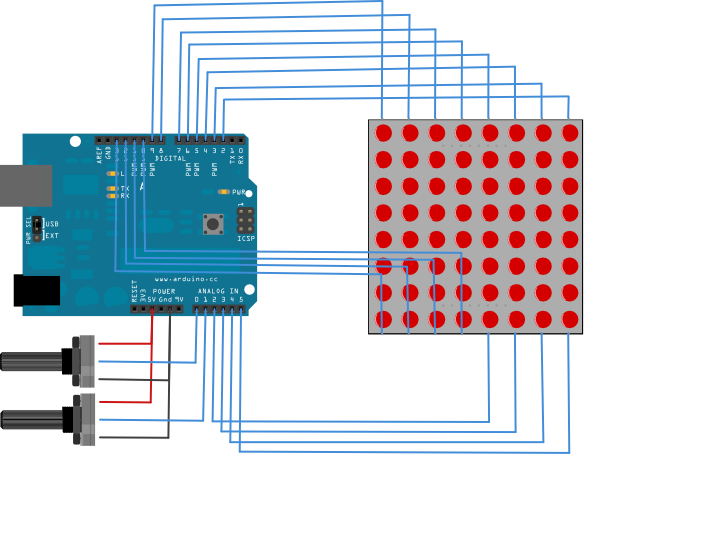
8×8LEDマトリクスを制御するための行コラムスキャン
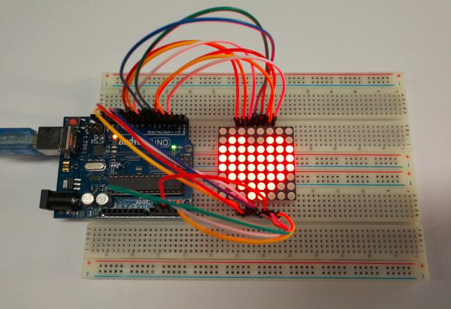
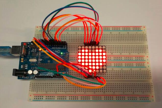
この例では、2つのアナログ入力を使って8×8 LEDマトリックスを制御します。アナログピン0と1に接続された2つのポテンショメーターが、マトリックス内の点灯LEDの動きを制御します。
回路図
コードプログラム
以下のコード例をプログラムにコピーしてください。
const int row[8] = {
  2, 7, 19, 5, 13, 18, 12, 16
};

// 2-dimensional array of column pin numbers:
const int col[8] = {
  6, 11, 10, 3, 17, 4, 8, 9
};

// 2-dimensional array of pixels:
int pixels[8][8];

// cursor position:
int x = 5;
int y = 5;

void setup() {
  // initialize the I/O pins as outputs
  // iterate over the pins:
  for (int thisPin = 0; thisPin < 8; thisPin++) {
    // initialize the output pins:
    pinMode(col[thisPin], OUTPUT);
    pinMode(row[thisPin], OUTPUT);
    // take the col pins (i.e. the cathodes) high to ensure that
    // the LEDS are off:
    digitalWrite(col[thisPin], HIGH);
  }

  // initialize the pixel matrix:
  for (int x = 0; x < 8; x++) {
    for (int y = 0; y < 8; y++) {
      pixels[x][y] = HIGH;
    }
  }
}

void loop() {
  // read input:
  readSensors();

  // draw the screen:
  refreshScreen();
}

void readSensors() {
  // turn off the last position:
  pixels[x][y] = HIGH;
  // read the sensors for X and Y values:
  x = 7 - map(analogRead(A0), 0, 1023, 0, 7);
  y = map(analogRead(A1), 0, 1023, 0, 7);
  // set the new pixel position low so that the LED will turn on
  // in the next screen refresh:
  pixels[x][y] = LOW;

}

void refreshScreen() {
  // iterate over the rows (anodes):
  for (int thisRow = 0; thisRow < 8; thisRow++) {
    // take the row pin (anode) high:
    digitalWrite(row[thisRow], HIGH);
    // iterate over the cols (cathodes):
    for (int thisCol = 0; thisCol < 8; thisCol++) {
      // get the state of the current pixel;
      int thisPixel = pixels[thisRow][thisCol];
      // when the row is HIGH and the col is LOW,
      // the LED where they meet turns on:
      digitalWrite(col[thisCol], thisPixel);
      // turn the pixel off:
      if (thisPixel == LOW) {
        digitalWrite(col[thisCol], HIGH);
      }
    }
    // take the row pin low to turn off the whole row:
    digitalWrite(row[thisRow], LOW);
  }
}


