Note: ALL OSOYOO Products for Arduino are Third Party Board which is fully compatitable with Arduino
Content
- Introduction
- Preparations
- About the 8×8 LED Matrix
- Examples
Introduction
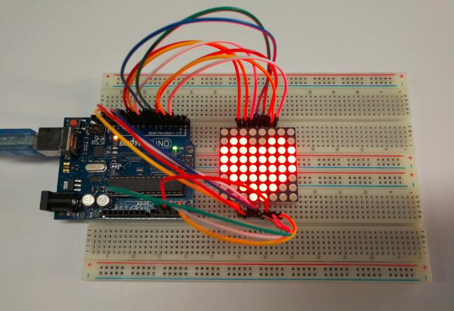
LED displays are often packaged as matrixes of LEDs arranged in rows of common anodes and columns of common cathodes, or the reverse.They can be used to display almost anything. Most modern LED sign boards uses various types of matrix boards with controllers. In this lesson we are going to interface a single color 8×8 LED matrix with Arduin and display a few characters to experience its charm from the beginning.
Preparations
Hardware
- Osoyoo UNO Board (Fully compatible with Arduino UNO rev.3) x 1
- 8×8 LED Matrix x 1
- 10k ohm Potentiometer x2
- M/M Jumpers
- Breadboard x 2
- USB Cable x 1
- PC x 1
Software
- Arduino IDE (version 1.6.4+)
About 8×8 LED Matrix
With low-voltage scanning, 8×8 LED Matrix LED display have advantages such as power saving, long service life, low cost, high brightness, a wide angle of view, long visual range, waterproofness, and so on. They can meet the needs of different applications and thus have a broad development prospect.
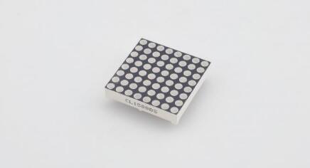
8×8 matrix consists of 64 dots or pixels. There is a LED for each pixel and these LEDs are connected to total of 16 pins.
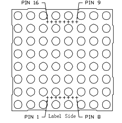
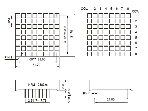
Generally, there are two types of dot matrix – common cathode and common anode. They look almost the same in appearance. But usually there will be labels for easy recognition. The one with a label ending with AX is a common cathode dot matrix and that with BXis a common anode one. See the figure below for how they look like. So the pins are distributed at the two ends of the matrix. Pins at one end (usually the label side) are 1-8 from left to right, when at the opposite they are 9-16 from right to left.
You can identify the pin out diagram of it using the following figure.
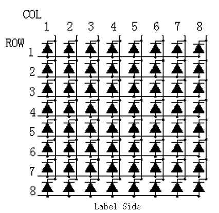
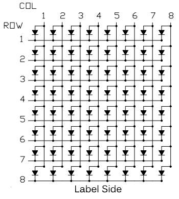
Below is the internal structure. You can see that in the common anode dot matrix, ROW is the anode of LED and COL is the cathode, while the situation in the common cathode one is opposite. Though for both types, the columns are the pin 13, 3, 4, 10, 6, 11, 15, and 16 and rows are the pin 9, 14, 8, 12, 1, 7, 2, and 5 in the dot matrix.
If you want to turn on all the LEDs at the first rTo light up the first LED on the upper left corner, you need to set pin 9 as high level and pin 13 as low level in the common anode dot matrix; for a common cathode one, set pin 13 as high and pin 9 as low. ow, in a common cathode dot matrix, set pin 13 as low level and ROW 9, 14, 8, 12, 1, 7, 2, and 5 as high level. In a common anode one, set pin 13 as high level and those rows as low level. See the figure below for better understanding.
Here’s a matrix of the pin connections, based on the diagram above:
| Matrix pin no. |
Row |
Column |
Arduin pin number |
| 1 |
5 |
– |
13 |
| 2 |
7 |
– |
12 |
| 3 |
– |
2 |
11 |
| 4 |
– |
3 |
10 |
| 5 |
8 |
– |
16 (analog pin 2) |
| 6 |
– |
5 |
17 (analog pin 3) |
| 7 |
6 |
– |
18 (analog pin 4) |
| 8 |
3 |
– |
19 (analog pin 5) |
| 9 |
1 |
– |
2 |
| 10 |
– |
4 |
3 |
| 11 |
– |
6 |
4 |
| 12 |
4 |
– |
5 |
| 13 |
– |
1 |
6 |
| 14 |
2 |
– |
7 |
| 15 |
– |
7 |
8 |
| 16 |
– |
8 |
9 |
You can see the dimension as below:
Note:
It doesn’t matter which pins of the microcontroller you connect the rows and columns to, because you can assign things in software. Connected the pins in a way that makes wiring easiest. We have 64 supply combinations, and doing it manually is practically impossible. This is why Arduin is interfaced with the 8×8 matrix.
Examples
Lights up an LED on the 8X8 matrix
As above subtitle, we will show how to light up an LED on the matrix.
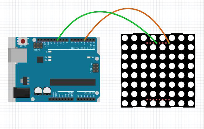
Circuit Diagram
To light up the first LED on the upper left corner, you need to set pin 9 as high level and pin 13 as low level in the common anode dot matrix; for a common cathode one, set pin 13 as high and pin 9 as low.
Upload Sketch
After above operations are completed, connect the board to your computer using the USB cable. The green power LED (labelled PWR) should go on.
Code Program
Copy the example code below into an program.
int pin3=3; //Connect the matrix pin 9 to Uno pin 3
int pin11=11;//Connect the matrix pin 13 to Uno pin 11
void setup() {
// put your setup code here, to run once:
pinMode(pin3,OUTPUT);
pinMode(pin11,OUTPUT);
digitalWrite(pin3,HIGH);
digitalWrite(pin11,HIGH);
}
void loop() {
  // put your main code here, to run repeatedly:
digitalWrite(pin11,LOW);//set the pin11 low,led will be turned on
delay(200);
digitalWrite(pin11,HIGH);//set the pin 11 high,led will be turned off。
delay(200);
}
Compile and upload
Open the Arduino IDE and select corresponding board type and port type for your board. After compile this sketch, simply click the “Upload” button in the environment. Wait a few seconds – you should see the RX and TX leds on the board flashing. If the upload is successful, the message “Done uploading.” will appear in the status bar.
Running Result
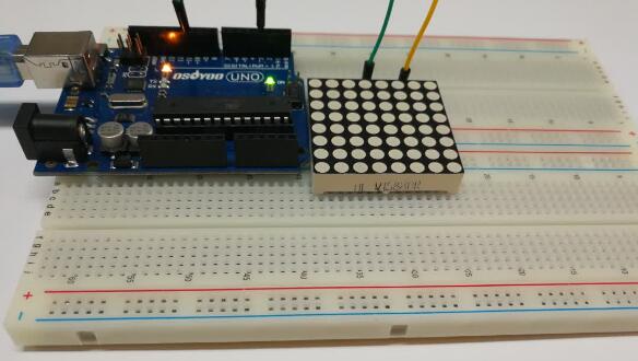
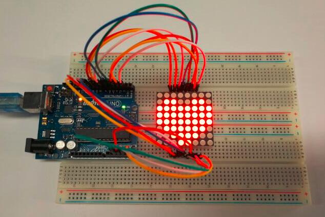
A few seconds after the upload finishes, you should now see the first LED on the upper left corner will blink:
Heart Blinking on the 8X8 matrix
Since the wiring of this experiment is a little complicated, we need to do it step by step.
Circuit Diagram
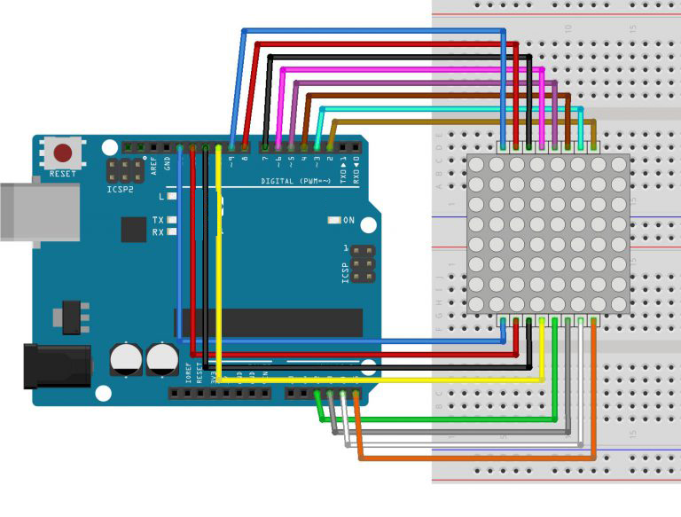
Code Program
Below is my code, you can download it here, note that I used the code from the Tutorials to work out how to get everything working.
// 2-dimensional array of row pin numbers:
int R[] = {2,7,A5,5,13,A4,12,A2};
// 2-dimensional array of column pin numbers:
int C[] = {6,11,10,3,A3,4,8,9};

unsigned char biglove[8][8] =     //the big "heart"
{
  0,0,0,0,0,0,0,0,
  0,1,1,0,0,1,1,0,
  1,1,1,1,1,1,1,1,
  1,1,1,1,1,1,1,1,
  1,1,1,1,1,1,1,1,
  0,1,1,1,1,1,1,0,
  0,0,1,1,1,1,0,0,
  0,0,0,1,1,0,0,0,
};

unsigned char smalllove[8][8] =      //the small "heart"
{
  0,0,0,0,0,0,0,0,
  0,0,0,0,0,0,0,0,
  0,0,1,0,0,1,0,0,
  0,1,1,1,1,1,1,0,
  0,1,1,1,1,1,1,0,
  0,0,1,1,1,1,0,0,
  0,0,0,1,1,0,0,0,
  0,0,0,0,0,0,0,0,
};

void setup()
{
   // iterate over the pins:
  for(int i = 0;i<8;i++)
  // initialize the output pins:
  {
    pinMode(R[i],OUTPUT);
    pinMode(C[i],OUTPUT);
  }
}

void loop()
{
  for(int i = 0 ; i < 100 ; i++)        //Loop display 100 times
  {
    Display(biglove);                   //Display the "Big Heart"
  }
  for(int i = 0 ; i < 50 ; i++)         //Loop display 50 times
  {
    Display(smalllove);                 //Display the "small Heart"
  }
}

void Display(unsigned char dat[8][8])
{
  for(int c = 0; c<8;c++)
  {
    digitalWrite(C[c],LOW);//use thr column
    //loop
    for(int r = 0;r<8;r++)
    {
      digitalWrite(R[r],dat[r][c]);
    }
    delay(1);
    Clear();  //Remove empty display light
  }
}

void Clear()                          //清空显示
{
  for(int i = 0;i<8;i++)
  {
    digitalWrite(R[i],LOW);
    digitalWrite(C[i],HIGH);
  }
}
Running Result
A few seconds after the upload finishes, you should now see a heart blink on the 8×8 LED matrix as below:
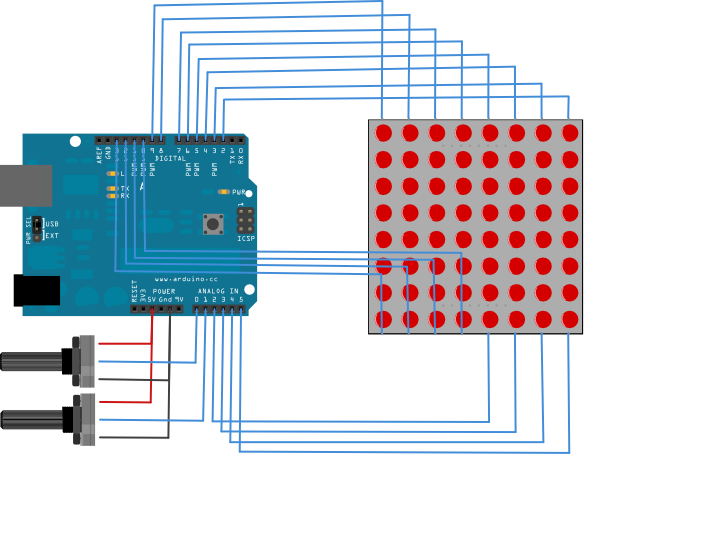
Row-columm Scanning to control an 8×8 LED Matrix
This example controls an 8×8 LED matrix using two analog inputs. Two potentiometers, connected to analog pins 0 and 1, control the movement of a lit LED in the matrix.
Circuit Diagram
Code Program
Copy the example code below into an program.
const int row[8] = {
  2, 7, 19, 5, 13, 18, 12, 16
};

// 2-dimensional array of column pin numbers:
const int col[8] = {
  6, 11, 10, 3, 17, 4, 8, 9
};

// 2-dimensional array of pixels:
int pixels[8][8];

// cursor position:
int x = 5;
int y = 5;

void setup() {
  // initialize the I/O pins as outputs
  // iterate over the pins:
  for (int thisPin = 0; thisPin < 8; thisPin++) {
    // initialize the output pins:
    pinMode(col[thisPin], OUTPUT);
    pinMode(row[thisPin], OUTPUT);
    // take the col pins (i.e. the cathodes) high to ensure that
    // the LEDS are off:
    digitalWrite(col[thisPin], HIGH);
  }

  // initialize the pixel matrix:
  for (int x = 0; x < 8; x++) {
    for (int y = 0; y < 8; y++) {
      pixels[x][y] = HIGH;
    }
  }
}

void loop() {
  // read input:
  readSensors();

  // draw the screen:
  refreshScreen();
}

void readSensors() {
  // turn off the last position:
  pixels[x][y] = HIGH;
  // read the sensors for X and Y values:
  x = 7 - map(analogRead(A0), 0, 1023, 0, 7);
  y = map(analogRead(A1), 0, 1023, 0, 7);
  // set the new pixel position low so that the LED will turn on
  // in the next screen refresh:
  pixels[x][y] = LOW;

}

void refreshScreen() {
  // iterate over the rows (anodes):
  for (int thisRow = 0; thisRow < 8; thisRow++) {
    // take the row pin (anode) high:
    digitalWrite(row[thisRow], HIGH);
    // iterate over the cols (cathodes):
    for (int thisCol = 0; thisCol < 8; thisCol++) {
      // get the state of the current pixel;
      int thisPixel = pixels[thisRow][thisCol];
      // when the row is HIGH and the col is LOW,
      // the LED where they meet turns on:
      digitalWrite(col[thisCol], thisPixel);
      // turn the pixel off:
      if (thisPixel == LOW) {
        digitalWrite(col[thisCol], HIGH);
      }
    }
    // take the row pin low to turn off the whole row:
    digitalWrite(row[thisRow], LOW);
  }
}


